Bone suppression in X-ray imaging

a bone suppression and x-ray imaging technology, applied in the field of medical x-ray imaging, can solve the problem that the suppression of bone structures is not readily applicable in cardiac angiography, and achieve the effect of facilitating perception and increasing details

Active Publication Date: 2018-01-23
KONINKLJIJKE PHILIPS NV
View PDF11 Cites 3 Cited by
  • Summary
  • Abstract
  • Description
  • Claims
  • Application Information

AI Technical Summary

Benefits of technology

[0004]There may thus be a need to provide improved X-ray images, for example for cardiac procedures, allowing a facilitated perception while ensuring that increased details are visible.
[0008]By suppressing bone structures only in selected areas of an X-ray image, the X-ray image presented to the user in form of the partly-bone-suppressed image provides detailed and undisturbed information in region of interest, while also providing the bone structures outside the identified suppression areas as anatomical markers, facilitating the navigation for the radiologist or surgeon.
[0030]In another example, the complete fluoroscopy image is transferred into the partly bone-suppressed angiogram image, wherein the fluoroscopy image may be adjusted in the grade of transparency for minimum distraction.
[0036]According to an exemplary embodiment, bone structures outside the suppression area are maintained and kept visible as anatomical markers, facilitating navigation.
[0040]According to an aspect, bone structures, such as ribs or other long bones, are suppressed from an X-ray exposure sequence in a controlled and local way, such that the position of an interventional device within the fluoroscopy image determines the area of suppression of the specific bone to be suppressed in the angiogram. A full suppression image for every detected bone may be computed and the suppression may be visualized only around the detected device position, e.g. in a circular fashion, feathering the borders. A region of interest around the detected device position may be checked for intersection with bones. For example, each bone that intersects with this region of interest is suppressed along its complete detected length. In another example, bone structures are manipulated in the image, for example completely deleted or at least attenuated in their appearance, in certain areas only, for example in an area of specific interest, such as the area where a device is located. Bones overlapping with the region of interest may be completely suppressed or all bones are faded out in the region of interest. Bone structures outside the particularly defined, i.e. selected area may be left untouched and are displayed to provide further orientation for navigation. The orientation facilitates the navigation in terms of better orientation in a larger scale, whereas the suppressed areas, i.e. areas where the bone structures are suppressed, show enhanced details that are no longer disturbed in terms of visual perception and mental understanding on the side of the user, since these selected or determined regions show the complete anatomical content, except the bone structures, which are suppressed.

Problems solved by technology

However, it has been shown that in X-ray imaging, for example during cardiac or vascular interventions or in diagnostic X-ray for soft tissue imaging, bone structures may superpose with the target anatomy and thus might prevent or complicate perception of faint or subtle structures.
However, this is not readily applicable to suppress bone structures during cardiac angiography, because the rib appearance may be very similar to the one of small injected vessels.

Method used


Image

  • Bone suppression in X-ray imaging
  • Bone suppression in X-ray imaging
  • Bone suppression in X-ray imaging

Examples


Embodiment Construction

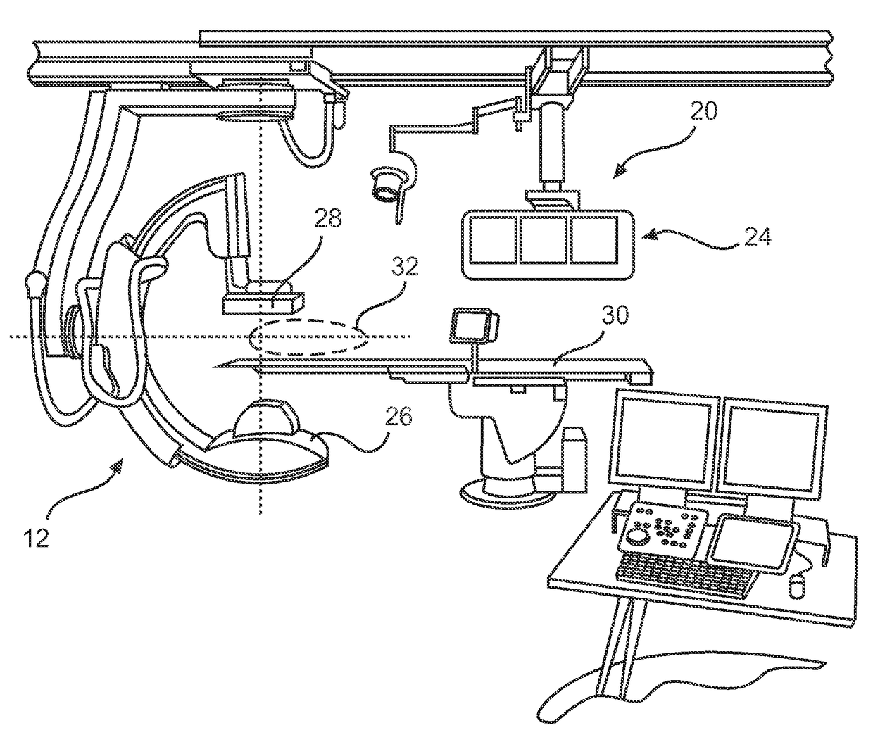
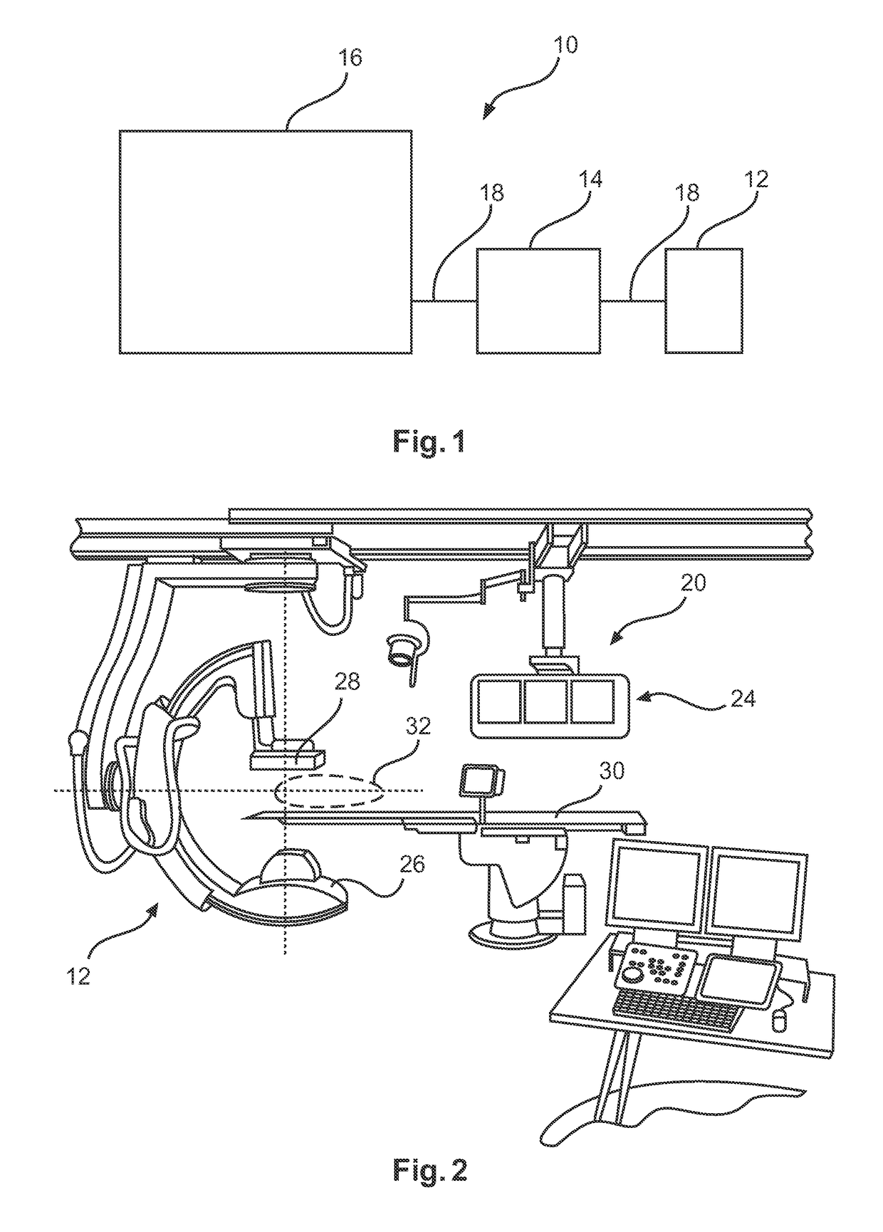
[0047]FIG. 1 shows a medical image viewing device 10 for navigation in X-ray imaging, wherein the medical image viewing device 10 comprises an image data providing unit 12, a processing unit 14, and a display unit 16. The image data providing unit 12 is configured to provide an angiographic image of a region of interest of an object. The processing unit 14 is configured to identify a suppression area for partial bone suppression within the angiographic image, and to identify and locally suppress predetermined bone structures in the angiographic image in the suppression area, to generate a partly-bone-suppressed image. The display unit 16 is configured to display the partly-bone-suppressed image. Connecting lines 18 indicate data connection between the image data providing unit 12, the processing unit 14, and the display unit 16. The data connection can be provided by wire connection and by wireless connection.

[0048]The term “suppression area” relates to a selected portion of the ima...


PUM


Abstract

The present invention relates to medical image viewing in relation with navigation in X-ray imaging. In order to provide improved X-ray images, for example for cardiac procedures, allowing a facilitated perception while ensuring that increased details are visible, a medical image viewing device (10) for navigation in X-ray imaging is provided that comprises an image data providing unit (12), a processing unit (14), and a display unit (16). The image data providing unit is configured to provide an angiographic image of a region of interest of an object. The processing unit is configured to identify a suppression area for partial bone suppression within the angiographic image, and to identify and locally suppress predetermined bone structures in the angiographic image in the suppression area, and to generate a partly-bone-suppressed image. Further, the display unit is configured to display the partly-bone-suppressed image.

Description

CROSS-REFERENCE TO PRIOR APPLICATIONS[0001]This application is the U.S. National Phase application under 35 U.S.C. §371 of International Application Serial No. PCT / IB2013 / 059096, filed on Oct. 3, 2013, which claims the benefit of U.S. Application Ser. No. 61 / 710,101, filed on Oct. 5, 2012. These applications are hereby incorporated by reference herein.FIELD OF THE INVENTION[0002]The present invention relates to medical X-ray imaging, and relates in particular to a medical image viewing device for navigation in X-ray imaging, a medical imaging system, a method for providing improved X-ray image navigation information, as well as to a computer program element and a computer readable medium.BACKGROUND OF THE INVENTION[0003]X-ray imaging is used, for example, during minimal invasive interventions, such as percutaneous cardiac interventions. To support navigation of an interventional device, fluoroscopic imaging, i.e. low dose X-ray imaging is used to visualize the current situation, for...

Claims


Application Information

Patent Timeline
Patent Type & Authority Patents(United States)
IPC IPC(8): G06T5/50G06T5/00A61B6/12G06T7/20A61B90/00A61B6/00
CPCG06T5/50A61B6/463A61B6/487A61B6/504G06T5/008G06T7/20A61B6/12G06T2211/404A61B6/4441A61B6/503A61B2090/364A61B2090/376G06T2207/10016G06T2207/10116G06T2207/10121G06T2207/30008G06T2207/30048G06T2207/30101
Inventor GOOSSEN, ANDREFLORENT, RAOULLEVRIER, CLAIREVON BERG, JENS
Owner KONINKLJIJKE PHILIPS NV
Why Eureka
Try Eureka