
Image processing apparatus and image processing method generating quantized data based on a determined print operation

a quantized data and image processing technology, applied in the field of image processing apparatus, image processing method, storage medium, can solve the problems of loss of dispersibility, inability to detect graininess, and difficulty in detecting defects, so as to prevent defects associated, suppress graininess, and appear easily

Active Publication Date: 2018-01-23
CANON KK
View PDF26 Cites 5 Cited by
  • Summary
  • Abstract
  • Description
  • Claims
  • Application Information

AI Technical Summary

Benefits of technology

The solution effectively prevents image defects associated with print position displacement while achieving suppressed graininess and superior dispersibility in mixed color images, even when print position displacement occurs.

Problems solved by technology

In the case of such a dither method, in particular, dot dispersibility in a low gradation range becomes problematic; however, as a threshold value matrix for obtaining preferable dot dispersibility, a threshold value matrix having blue noise characteristics is proposed.
However, even in the case of using a threshold value matrix having blue noise characteristics, in the case of printing an image using multiple color materials (i.e., mixed color), dispersibility is lost to make graininess conspicuous in some cases.
However, the method disclosed in U.S. Pat. No. 6,867,884 focuses on graininess and dispersibility in a mixed color image, but does not focus on any defect associated with print position displacement among color materials.
That is, in a configuration where a print head is prepared for each of color materials to be printed, if relative print position displacement occurs among the print heads due to some cause, density unevenness and color unevenness are caused on an image.
In addition, such unevenness is repeated with a period corresponding to the size of a dither matrix, and easily recognized as image defects.

Method used


Image

  • Image processing apparatus and image processing method generating quantized data based on a determined print operation
  • Image processing apparatus and image processing method generating quantized data based on a determined print operation
  • Image processing apparatus and image processing method generating quantized data based on a determined print operation

Examples


first embodiment

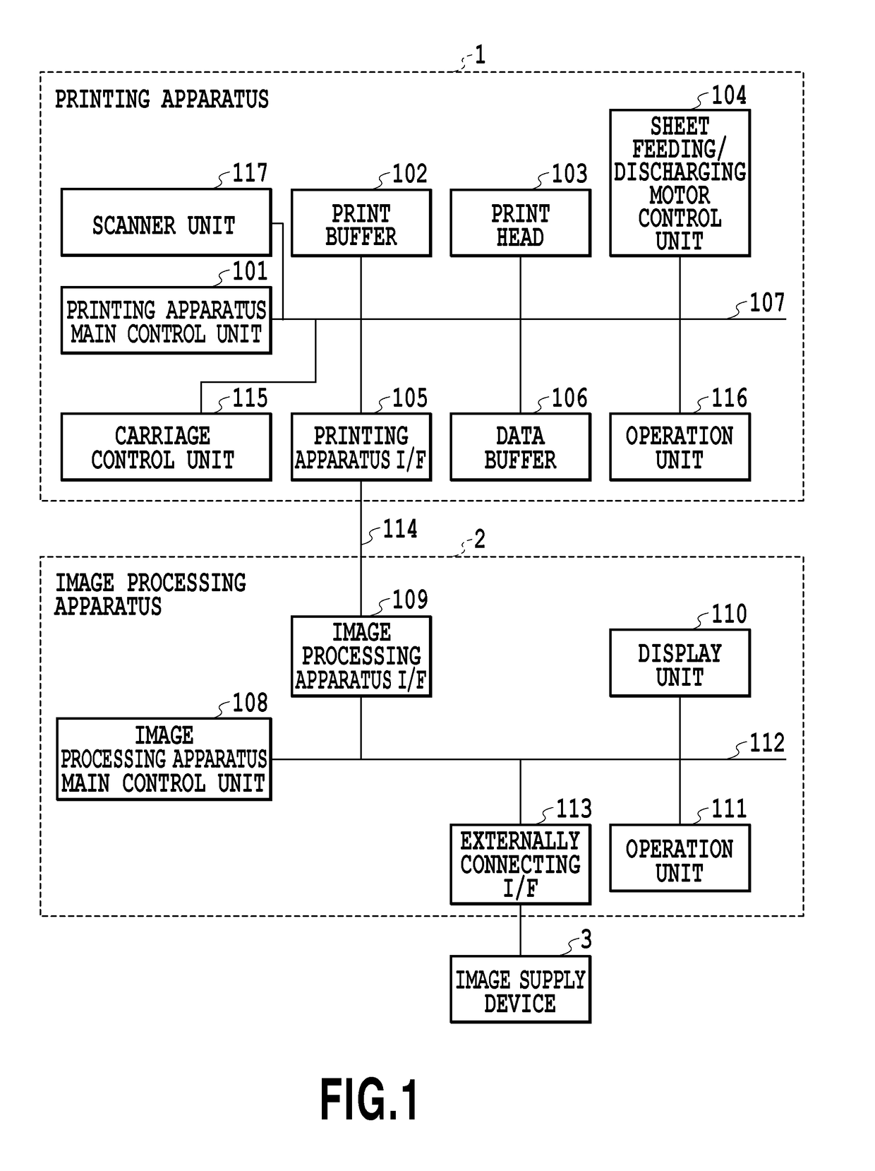
[0029]FIG. 1 is a block diagram illustrating the control configuration of an inkjet printing system applicable to the present invention. The inkjet printing system in the present embodiment is configured to include an image supply device 3, an image processing apparatus 2, and an inkjet printing apparatus 1 (hereinafter also simply referred to as a printing apparatus). Image data supplied from the image supply device 3 is subjected to a predetermined image process in the image processing apparatus 2, then sent to the printing apparatus 1, and printed.

[0030]In the printing apparatus 1, a printing apparatus main control unit 101 is one for controlling the whole of the printing apparatus 1, and configured to include a CPU, ROM, RAM, and the like. The printing apparatus main control unit 101 can variously change a printing method depending on a set print mode. For example, when a marginless print mode is set, the printing apparatus main control unit 101 controls the ejection action of a...

second embodiment

[0099]In the first embodiment, described is the configuration where the multiple threshold value matrices having various sizes and shapes are preliminarily stored in the fixed memory 310, and from among the threshold value matrices, the threshold value acquisition unit 305 selects a threshold value matrix corresponding to a print mode. On the other hand, the present embodiment is configured to use a rewritable storage area incorporated in a processing circuit as a memory 310, and externally read and use a threshold value matrix to be used. In such a memory configuration, although high-speed processing is achievable, cost and power consumption are large, and therefore it is preferable to efficiently utilize the memory 310 while using the smallest possible capacity.

[0100]FIGS. 11A and 11B are block diagrams for explaining a first dither process and a second dither process in the present embodiment. In the case of performing the first dither process, as illustrated in FIG. 11A, a thres...


PUM


Abstract

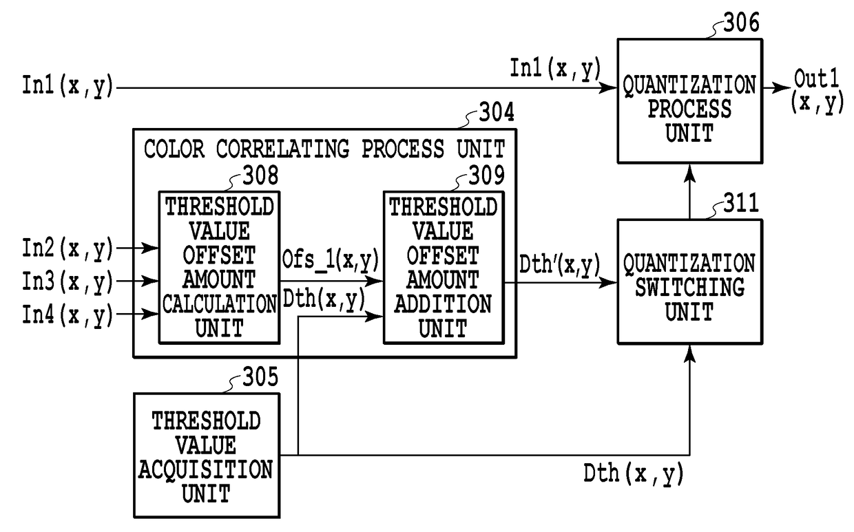
An image processing apparatus has a determination unit that determines a print operation to be performed and a generation unit that generates quantized data for printing a dot by comparing a threshold value and the multi-valued data. In a case of performing a first print operation, dot arrangement of the multiple types of inks printed on the print medium by the print unit on a basis of pieces of quantized data generated by the generation unit is higher in exclusiveness and dispersibility between or among dots of the multiple types of inks and lower in an overlap rate between or among the dots of the multiple types of inks than dot arrangement of the multiple types of inks printed on the print medium by the print unit on a basis of the pieces of quantized data generated by the generation unit in the case of performing the second print operation.

Description

BACKGROUND OF THE INVENTION[0001]Field of the Invention[0002]The present invention relates to an image processing apparatus, image processing method, and storage medium for performing a quantization process to form an image on a print medium.[0003]Description of the Related Art[0004]In the case of using a pseudo gradation method to print an image, it is necessary to quantize multi-valued image data, and as a quantization method used for the quantization, an error diffusion method and a dither method are known. In particular, the dither method that compares a preliminarily stored threshold value and a gradation value of multi-valued data with each other to determine dot printing or non-printing has a small processing load as compared with the error diffusion method, and is therefore widely used in many image processing apparatuses. In the case of such a dither method, in particular, dot dispersibility in a low gradation range becomes problematic; however, as a threshold value matrix ...

Claims


Application Information

Patent Timeline
Patent Type & Authority Patents(United States)
IPC IPC(8): H04N1/52
CPCH04N1/52H04N1/405H04N1/4053H04N1/58
Inventor YAMADA, AKITOSHIMIYAZAKI, SHINICHIKATO, MASAO
Owner CANON KK
Learn More