Nuclear powered rotary internal engine apparatus

a technology of internal combustion engine and nuclear power, applied in the field of nanotechnology, can solve the problems of limited resources, current fossil fuel use rate rapidly decreasing supply, greenhouse gas known to have negative impact on the environment, etc., and achieve the effect of reducing neutron leakage and improving the performance of the internal combustion engin

Active Publication Date: 2018-01-30
GLOBAL ENERGY RES ASSOC
View PDF61 Cites 1 Cited by
  • Summary
  • Abstract
  • Description
  • Claims
  • Application Information

AI Technical Summary

Benefits of technology

[0071]According to an exemplary embodiment, the nanofuel engine apparatus may include where performance of the internal combustion engine may be improved by decreasing an engine core surface to volume ratio, where the engine core surface to volume ratio is proportional to the neutron leakage.
[0072]According to an exemplary embodiment, the nanofuel engine apparatus may include where the internal combustion engine may include a reciprocating engine geometry, where the reciprocating engine geometry has an engine core, where the engine core has a cylindrical shape, which may include a cylinder radius R and a cylinder height H, where when the internal combustion engine is in a top dead center (TDC) position the engine core may include at least one of about, or approximately H=2R and / or may reduce neutron leakage, and where a critical radius Rc of the engine core may be between 30 cm and 70 cm, where the critical radius Rc is inversely proportional to a compression ratio r (Rc˜1 / r), and where the nanofuel engine apparatus is supercritical when the cylinder radius is greater than the critical radius (R>Rc).
[0074]According to an exemplary embodiment, the nanofuel engine apparatus may further include a closed thermodynamic fuel cycle that may continuously recycle the nanofuel. Recycling may maximize fuel utilization, in an exemplary embodiment.
[0082]According to an exemplary embodiment, the nanofuel engine apparatus may include where the at least one of: may act as a radioactive nuclear waste burner; may release less energy per mass of the nanofuel with the LWR SNF as compared to the nanofuel without the LWR SNF, for the nanofuel with a substantially equivalent composition; and / or may require a larger volume to release a substantially equivalent amount of energy using the nanofuel with the LWR SNF as compared to the nanofuel without the LWR SNF, for the nanofuel with a substantially equivalent composition. In an exemplary embodiment, the radioactive waste burner may produce clean energy, and / or reduce geological storage requirements for the LWR SNF.
[0145]According to an exemplary embodiment, the method may include where the (ii) may include: where the releasing energy until the engine core gets too large with respect to the criticality, where the criticality may relate to a reflector of the nanofuel engine, where the reflector may reduce neutron leakage, and where the reflector may include at least one of: making the nanofuel engine smaller than without the reflector; or slowing down and returning fast neutrons back into the nanofuel by a finite thickness of the reflector.
[0150]According to an exemplary embodiment, the method may include where the nanofuel engine may include a rotary engine, where the rotary engine may include a rotor, where the rotor may include a rotor cavity shape, which may include at least one of: an arbitrary shape, a cylindrical shape, an ellipsoidal shape, a rectangular shape, and / or a spherical shape; and where performance of the rotary engine may be improved by decreasing the rotor cavity shape surface to volume ratio.

Problems solved by technology

Conventional IC engines use fossil fuels, which are a limited resource.
Unfortunately, the present rate of fossil fuel use is rapidly decreasing supply.
Also, the combustion of fossil fuels produces carbon dioxide (CO2), which is a greenhouse gas known to have a negative impact on the environment.

Method used


Image

  • Nuclear powered rotary internal engine apparatus
  • Nuclear powered rotary internal engine apparatus
  • Nuclear powered rotary internal engine apparatus

Examples


Embodiment Construction

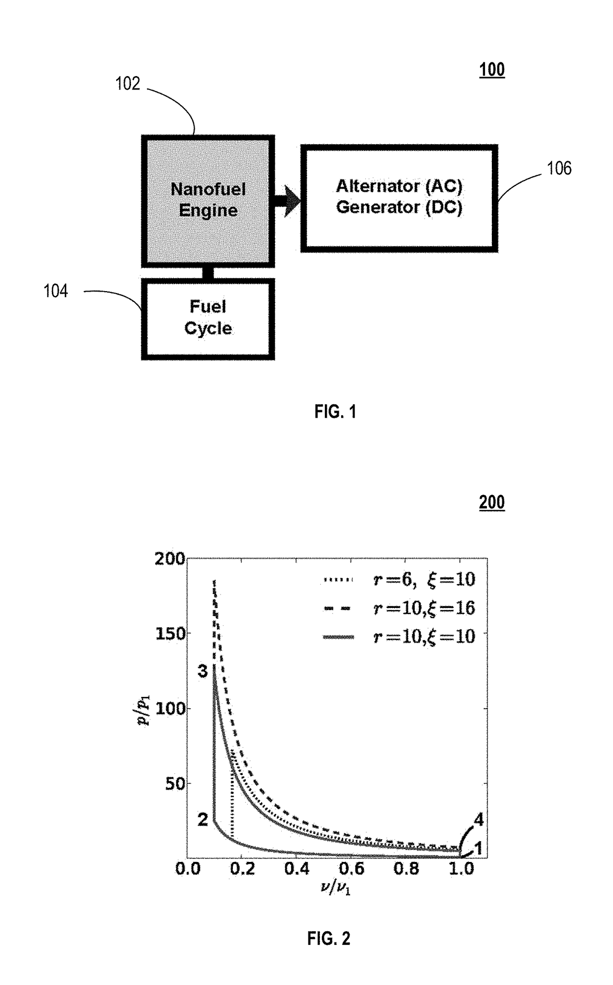
[0009]Various exemplary embodiments of an apparatus, system, method and / or computer program product for providing a nanofuel-based exemplary nanofuel engine apparatus and exemplary power generation systems, according to various exemplary apparatuses, and methods are set forth in detail herein, below.

[0010]According to an exemplary embodiment, an exemplary nanofuel engine apparatus may include an internal combustion engine adapted to receive a nanofuel that releases nuclear energy; and receive the nanofuel internal to the internal combustion engine.

[0011]According to an exemplary embodiment, the nanofuel engine apparatus may include where the nanofuel may include a moderator, a molecule with dimensions on a nanometer scale, and a molecular mixture.

[0012]According to an exemplary embodiment, the nanofuel engine apparatus may include where the internal combustion engine may further include a reflector.

[0013]According to an exemplary embodiment, the nanofuel engine apparatus may include...


PUM


Abstract

A nanofuel engine including receiving nanofuel (including moderator, nanoscale molecular dimensions & molecular mixture) internally in an internal combustion engine that releases nuclear energy, is set forth. A nanofuel chemical composition of fissile fuel, passive agent, and moderator. A method of obtaining transuranic elements for nanofuel including: receiving spent nuclear fuel (SNF); separating elements from SNF, including a stream of elements with Z>92, fissile fuel, passive agent, fertile fuel, or fission products; and providing elements. A method of using transuranic elements to create nanofuel, including: receiving, converting, and mixing the transuranic elements with a moderator to obtain nanofuel. A method of operating a nanofuel engine loaded with nanofuel in spark or compression ignition mode. A method of cycling a nanofuel engine, including compressing nanofuel; igniting nanofuel; capturing energy released in nanofuel, which is also the working fluid; and using the working fluid to perform mechanical work or generate heat.

Description

BACKGROUND OF THE INVENTION[0001]Field of the Invention[0002]Embodiments of the present invention relate generally to nanotechnology, and more particularly to energy applications of nanotechnology.[0003]Discussion of the Related Art[0004]After several centuries of development, conventional internal-combustion (IC) engines are now the most reliable and widely used power source in the world, as of 2013. Notable historical milestones of the IC engine include, the first gunpowder IC engine in 1678 by Christiaan Huygens and the first commercial IC engine in 1858 by Jean Lenoir.[0005]Modern IC engines may rely on an explosive mixture of fossil fuel and air to generate heat and produce useful mechanical work. While numerous IC engine designs exist, the designs all tend to perform the following processes: intake, where a working fluid enters the engine; compression, where the working fluid experiences a decrease in volume; combustion, where the working fluid experiences a rapid increase in ...

Claims


Application Information

Patent Timeline
Patent Type & Authority Patents(United States)
IPC IPC(8): F01C21/08G21C3/42G21C19/42G21C1/32F02B53/00G21D5/02B63G8/08B64G1/40
CPCG21D5/02F01C21/08G21C1/32G21C3/42G21C19/42Y02E30/38B63G8/08B64G1/408F02B2053/005Y02E30/00Y02E30/30
Inventor ADAMS, MARK LLOYD
Owner GLOBAL ENERGY RES ASSOC
Why Eureka
Try Eureka