Output amplifier and display driver

a technology of output amplifier and display driver, which is applied in the direction of differential amplifiers, amplifiers with semiconductor devices/discharge tubes, instruments, etc., can solve the problems of deterioration of drivability, gate potential of p-channel transistors falling too much, and gate potential of n-channel transistors rising too much, so as to reduce the distortion of output waveform

Active Publication Date: 2019-01-10
LAPIS SEMICON CO LTD
View PDF1 Cites 6 Cited by
  • Summary
  • Abstract
  • Description
  • Claims
  • Application Information

AI Technical Summary

Benefits of technology

[0010]As a method for compensating for deterioration in the drivability of each transistor in the output stage due to the drop of the power voltage VDD, it is conceivable to increase a gate width of each transistor. However, this method causes an increased chip size. There is also a problem that increased wiring and an increased parasitic capacity of each transistor cause an increase in parasitic capacities of internal nodes in the output stage, thus resulting in deterioration in characteristics, such as an increased delay time of the output waveform and worse heat generation.
[0011]In view of the above-described problems, the present invention has an object of providing an output amplifier that can effectively reduce a distortion of an output waveform at the time of rising of a display driver, and the display driver including the output amplifiers.
[0014]According to the output amplifier of the present invention, it is possible to effectively reduce a distortion of an output waveform at the time of rising of the display driver.

Problems solved by technology

The drop of the power voltage VDD causes a reduction in a gate-source voltage Vgs of a P-channel transistor in an output stage, thus resulting in deterioration of drivability.
Therefore, when the output of the positive output amplifier reaches the target potential, the gate potential of the P-channel transistor has fallen too much.
Therefore, when an output of the negative output amplifier reaches a target potential, the gate potential of the N-channel transistor has risen too much.

Method used


Image

  • Output amplifier and display driver
  • Output amplifier and display driver
  • Output amplifier and display driver

Examples


Embodiment Construction

[0025]An embodiment of the present invention will be described below with reference to the drawings. In the following description and accompanying drawings of the embodiment, the same reference numerals indicate the substantially same or equivalent components.

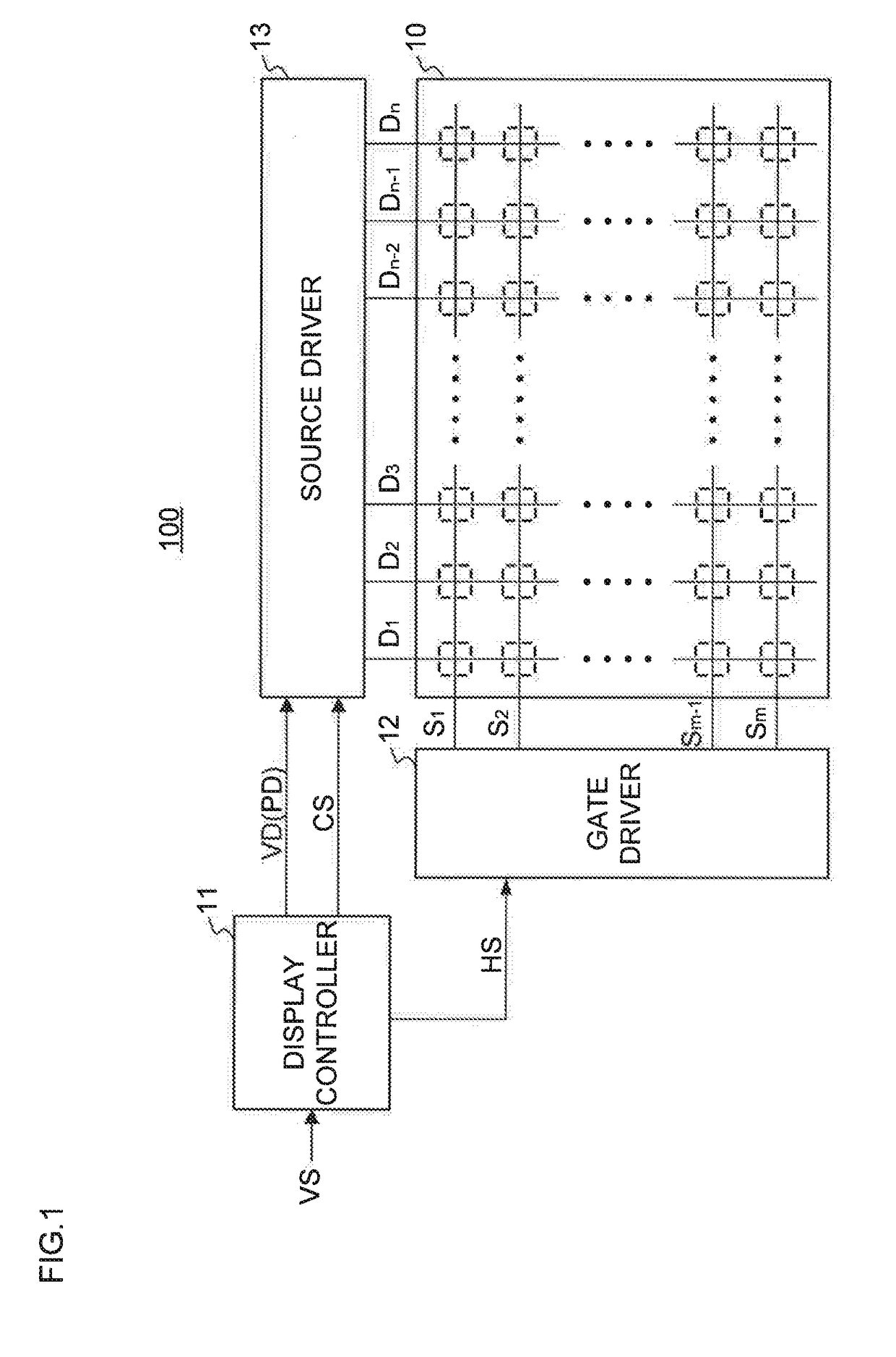
[0026]FIG. 1 is a block diagram showing a schematic configuration of a display apparatus 100 including output amplifiers according to the embodiment. The display apparatus 100 is a liquid crystal display apparatus that drives a display device 10 composed of, for example, a liquid crystal display or the like, by an inversion driving method. The display apparatus 100 includes the display device 10, a display controller 11, a gate driver 12, and a source driver 13.

[0027]In the display device 10, an m (m is an integer of 2 or more) number of horizontal scan lines S1 to Sm extending in a horizontal direction of a two-dimensional screen, and an n (n is an integer of 2 or more) number of data lines D1 to Dn extending in a vertical dir...


PUM


Abstract

Provided is an output amplifier including a differential unit which sends a current corresponding to a voltage difference between a gradation voltage and an amplified gradation voltage to a first current line; a current mirror unit which sends an amount of current corresponding to the current flowing through the first current line, to a second current line; and an output unit including a first and a second drive line, an output line through which the amplified gradation voltage is output, a first output transistor which sends a current based on a voltage of the first drive line, and a second output transistor which sends a current based on a voltage of the second drive line. The output unit includes a voltage regulation circuit which controls the voltage of the first drive line being higher than the voltage of the second drive line.

Description

BACKGROUND OF THE INVENTION1. Field of the Invention[0001]The present invention relates to an output amplifier that amplifies a gradation voltage based on a video signal, and a display driver including the output amplifiers.2. Description of the Related Art[0002]In display apparatus including display panels such as liquid crystal panels, display drivers which are configured to drive the display apparatus apply voltages in accordance with gradation levels of image data to the display panels in order to display images thereon. At this time, for the purpose of preventing degradation in the characteristics of liquid crystal materials, an inversion driving method is generally used in which the voltages to be applied to the liquid crystal are inverted at constant intervals. The display driver adopting the inversion driving method has, for example, a positive output amplifier and a negative output amplifier, and applies the gradation voltages to source lines while switching polarity betwee...

Claims


Application Information

Patent Timeline
Patent Type & Authority Applications(United States)
IPC IPC(8): G09G3/36H03F3/45
CPCG09G3/3696H03F3/45179G09G2320/0233H03F2203/45116G09G2310/0291H03F2200/129G09G3/3688G09G2320/0204H03F3/45219
Inventor SHIIBAYASHI, KENICHI
Owner LAPIS SEMICON CO LTD
Why Eureka
Try Eureka