
Display controlling system utilizing non-identical transfer pulse signals to control display and controlling method thereof

a control system and non-identical technology, applied in the field of display, can solve the problems of insufficient turning off, delay of gate signal along the activated gate line, and affect image quality, and achieve the effect of increasing the pulse width of the gate signal and not needing to shorten the gate signal

Inactive Publication Date: 2013-06-04
HIMAX TECH LTD
View PDF4 Cites 3 Cited by
  • Summary
  • Abstract
  • Description
  • Claims
  • Application Information

AI Technical Summary

Benefits of technology

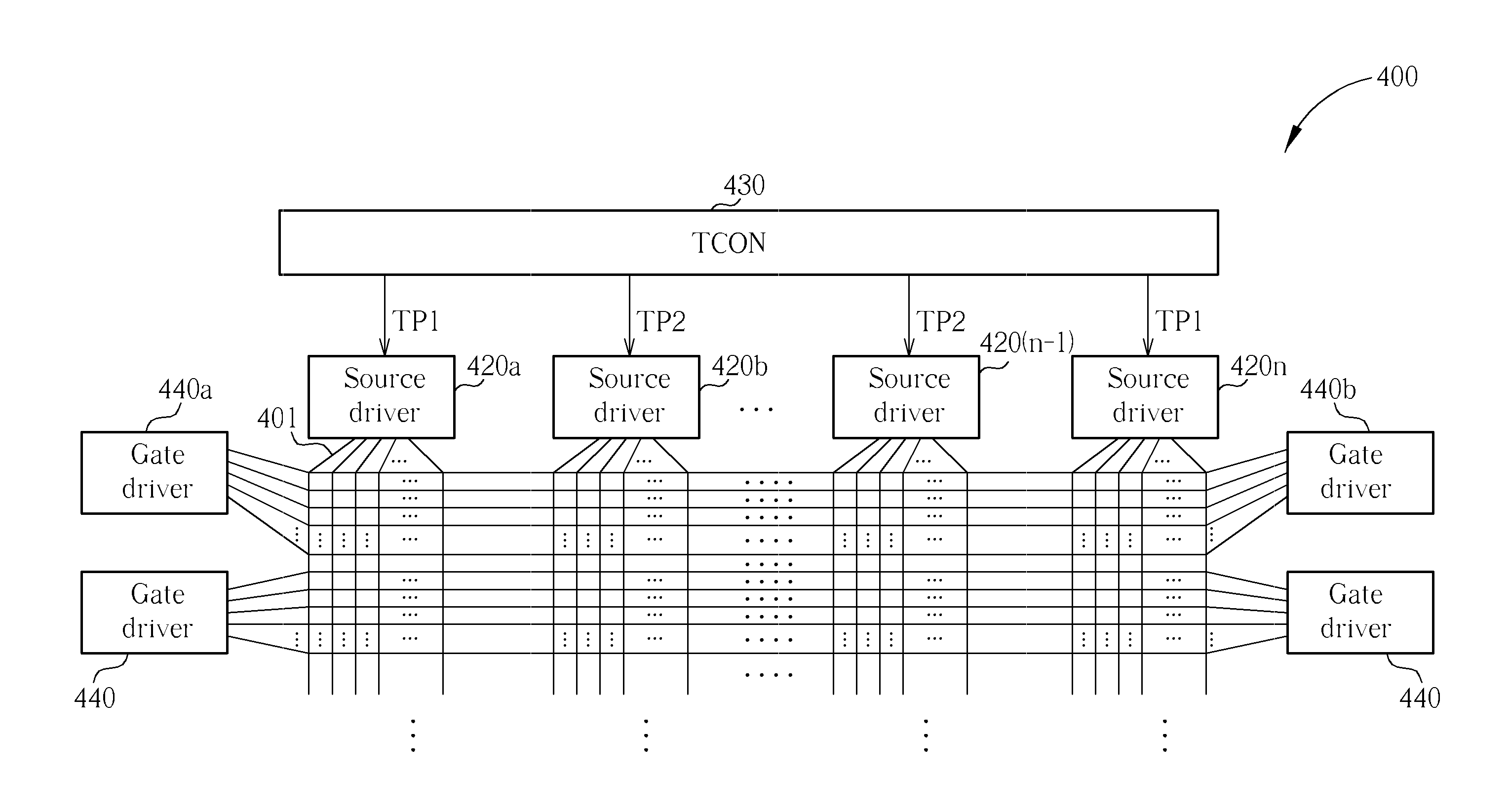
[0007]One objective of the present invention is therefore to provide a display controlling system and a controlling method thereof that solve the above problems. The display controlling system utilizes a plurality of non-identical transfer pulse signals to control the display rather than utilizing one single transfer pulse signal. Each source driver is provided with a dedicated transfer pulse signal, and therefore the gate signal does not need to be shortened. Since the pulse width of the gate signal can be increased, the present invention is suitable for a high-frequency operation environment.
[0008]Moreover, the transfer pulse information required for generating the transfer pulse signals can be embedded in the source data. The source drivers generate the transfer pulse signals after receiving the source data. In this way, the transfer pulse signal lines between the timing controller and the source drivers can be removed to save production cost.

Problems solved by technology

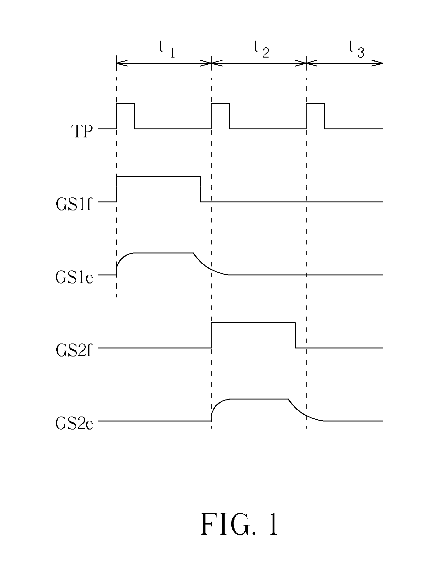
However, there exists gate delays along the activated gate line, due to that each gate lines has parasitic resistors and parasitic capacitors.
It can be seen at the beginning of the second line period t2 that the pixels of the second gate line receives the gate signal GS2 and thus activated, however, the ending pixels of the first gate line may be not fully turned off due to the shape of GS1e, therefore the image quality is affected.
Shortening the pulse width of the gate signal, however, causes the problem that the charging time of the pixels is also shortened; the pixels may not have enough time to be charged to their target display voltage levels, especially when the panel is operated at high frequency.

Method used


Image

  • Display controlling system utilizing non-identical transfer pulse signals to control display and controlling method thereof
  • Display controlling system utilizing non-identical transfer pulse signals to control display and controlling method thereof
  • Display controlling system utilizing non-identical transfer pulse signals to control display and controlling method thereof

Examples


Embodiment Construction

[0020]Certain terms are used throughout the description and following claims to refer to particular components. As one skilled in the art will appreciate, manufacturers may refer to a component by different names. This document does not intend to distinguish between components that differ in name but not function. In the following description and in the claims, the terms “include” and “comprise” are used in an open-ended fashion, and thus should be interpreted to mean “include, but not limited to . . . ”. Also, the term “couple” is intended to mean either an indirect or direct electrical connection. Accordingly, if one device is coupled to another device, that connection may be through a direct electrical connection, or through an indirect electrical connection via other devices and connections.

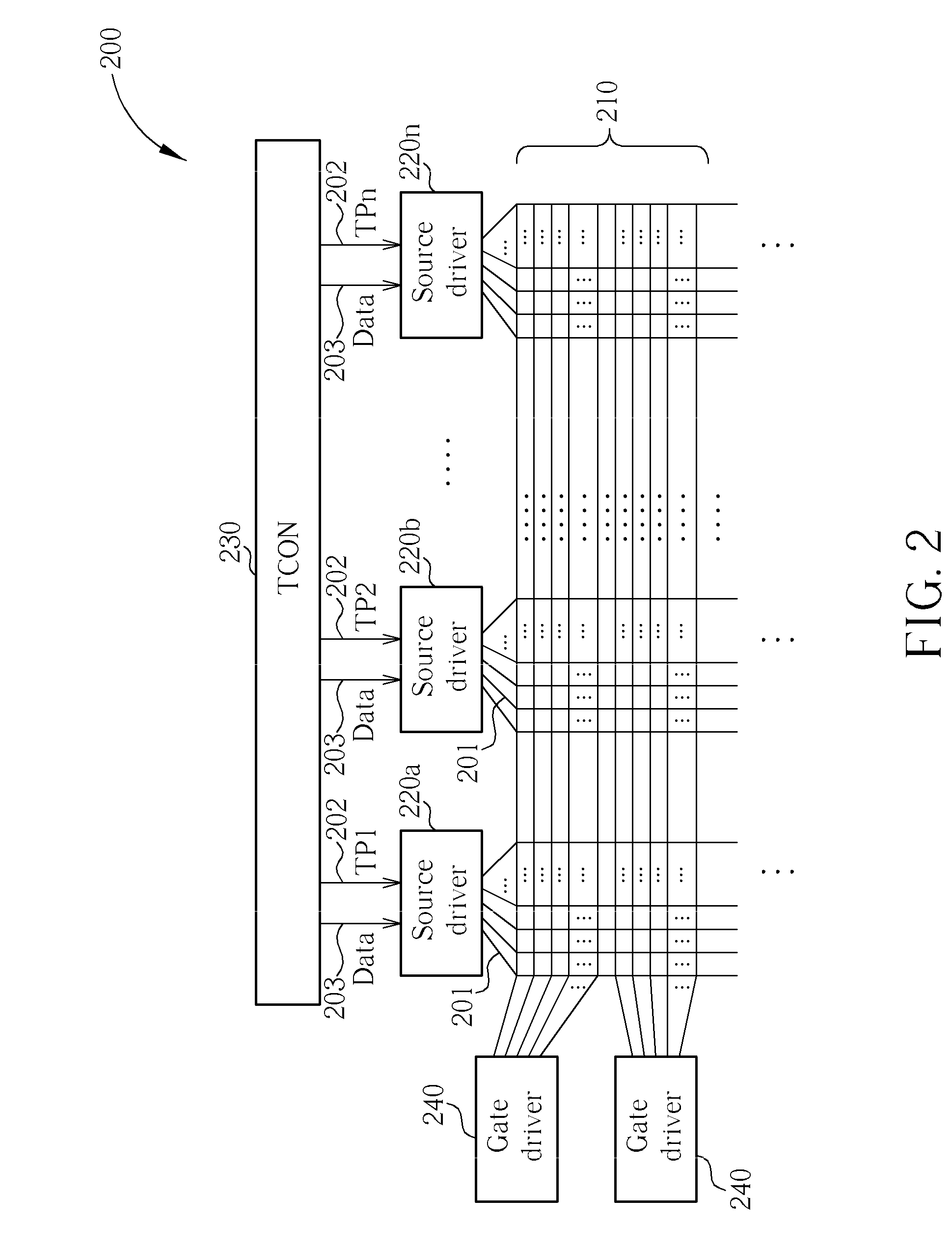
[0021]FIG. 2 illustrate a diagram of a display 200. The display 200 comprises a panel 210, a plurality of source drivers 220, gate drivers 240 and a timing controller (TCON) 230. The timing c...


PUM


Abstract

A display controlling system utilized in a display, such as an LCD, includes a plurality of data lines and a plurality of source drivers. The source drivers receive a plurality of transfer pulse signals, each of which corresponds to one of the source drivers, and drive the corresponding data lines upon receiving the corresponding transfer pulse signal, wherein the transfer pulse signals are not all identical. The transfer pulse signal can be produced by the timing controller of the display, or the transfer pulse information required for generating the transfer pulse signals can be embedded in the source data to be delivered to the source drivers that generate the transfer pulse signals after obtaining the transfer pulse information. The transfer pulse signal lines between the timing controller and the source drivers can therefore be removed.

Description

BACKGROUND OF THE INVENTION[0001]1. Field of the Invention[0002]The present invention relates to a display, and more particularly, to a display and a method for controlling same.[0003]2. Description of the Prior Art[0004]Conventionally, a liquid crystal display (LCD) includes a plurality of source drivers, gate drivers, and a timing controller. The timing controller (TCON) is connected to the source drivers to transmit data and control timings. First the gate drivers output a gate signal to activate a gate line, and once the source drivers receive a transfer pulse signal TP from the timing controller, each of the source drivers drives its corresponding data lines, which means that corresponding display voltages are simultaneously supplied to a row of pixels corresponding to the activated gate line in the LCD.[0005]However, there exists gate delays along the activated gate line, due to that each gate lines has parasitic resistors and parasitic capacitors. As can be seen from FIG. 1, ...

Claims


Application Information

Patent Timeline
Patent Type & Authority Patents(United States)
IPC IPC(8): G09G3/36
CPCG09G3/3688G09G2370/08
Inventor WENG, MENG-TSECHEN, CHIEN-RU
Owner HIMAX TECH LTD
Learn More