System and method for influencing the induction gas temperature in the combustion chamber of an internal combustion engine

a technology of induction gas temperature and combustion chamber, which is applied in the direction of electrical control, process and machine control, instruments, etc., can solve the problems of inability to select and the need for compromis

Inactive Publication Date: 2008-07-15
SIEMENS AG
View PDF42 Cites 8 Cited by
  • Summary
  • Abstract
  • Description
  • Claims
  • Application Information

AI Technical Summary

Benefits of technology

[0011]The invention builds on the generic system in that the temperature increase of the fresh air from T1 to T2 is explicitly used to influence the temperature level and thereby the energy level in the combustion chamber. In this way very fine variations and settings of the energy level in the combustion chamber can be achieved by increasing the temperature or by regulating the air / fuel temperature. In this way the combustion process in the HCCI mode can be precisely controlled. The temperature level in the combustion chamber can in this case be influenced via the level of compression and the subsequent expansion.
[0013]The inventive system can then be used to particularly good effect if the compression device is an exhaust gas turbocharger. This is a frequently used device for increasing the gas density in the induction system, so that in the combustion chamber an increased volume or air can be provided which results in an increase in performance of the internal combustion engine. The compression device is driven by a turbine located in the exhaust gas stream.
[0018]The inventive system is advantageously further developed by the exhaust gas cooler being arranged in a separate heat exchanger circuit. The heat exchanger cooler can thus operate autonomously without being influenced by other components of the motor vehicle. Likewise other components of the cooling system of the vehicle are not influenced by the exhaust gas cooler. The autonomous cooling circuit then comprises a separate cooler and a separate coolant pump.
[0019]It can however also be useful for the exhaust gas cooler to be arranged in the engine coolant circuit. In this way components of the engine coolant circuit can be used for exhaust gas cooling, so that overall an efficient system is implemented.
[0084]The invention is based on the knowledge that, by explicitly influencing or explicitly taking into account the air / fuel temperature, very fine and precise control can be exerted on the energy level in the combustion chamber of the internal combustion engine. As well as the principle of exhaust gas recirculation, this makes a further available a further independent instrument for influencing the temperature level and thereby for combustion process control. The invention in particular offers the advantage that, starting from cold-start conditions, under which HCCI operation is not possible because the temperature level is too low, the air / fuel mixture is heated up and thus an earlier switchover into the lower-emission HCCI mode is possible. In an especially preferred embodiment it is especially useful that the controlled setting of the exhaust gas temperature by means of exhaust gas cooling, in addition to the exhaust gas recirculation rate and the principle of compression and expansion, makes available a further independent adjustment variable to influence the temperature level and thereby the energy level in the combustion chamber and thereby an additional means of controlling the combustion process. The influence of the process is exerted in respect of the ignition point of the compressed air / fuel / exhaust gas mixture and the resulting variables produced from it, such as pressure curve and combustion, peak pressure, 50% mass fraction burnt point and speed of combustion. These variables in their turn are decisively responsible for the overall engine behavior in respect of its efficiency, emissions, ride disturbance and acoustics. The invention ties in with the fact that in modern engine management systems all the relevant information and operating variables, for example temperatures and masses of materials or quantities, which are needed for control of the HCCI combustion process by means of exhaust gas temperature regulation are already available. The invention can also be effectively used to allow for changed environmental or operating conditions in combustion engines, as for example is the case for engine hot running or in summer / winter mode at greatly differing ambient temperatures.

Problems solved by technology

Since the exhaust gas recirculation rate influences not only the temperature level in the combustion chamber but also the mixture ratio of air, fuel and exhaust gas, it is under some circumstances not possible to select an exhaust gas recirculation rate which is optimum both with regard to the temperature in the combustion chamber and with regard to the said air-fuel mixture ratio.
Thus compromises can be necessary when setting the exhaust gas recirculation rate to ensure reliable operation of the internal combustion engine.

Method used


Image

  • System and method for influencing the induction gas temperature in the combustion chamber of an internal combustion engine
  • System and method for influencing the induction gas temperature in the combustion chamber of an internal combustion engine
  • System and method for influencing the induction gas temperature in the combustion chamber of an internal combustion engine

Examples


Embodiment Construction

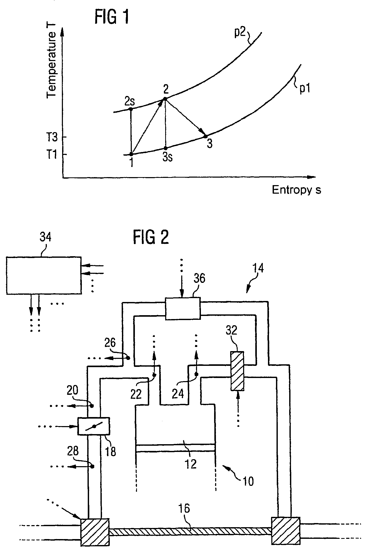
[0091]FIG. 1 shows a temperature-entropy diagram to explain the basic thermodynamic principles of a preferred embodiment of the present invention. The diagram shows the temperature-entropy graphs in a gas for two different pressures p1 and p2. If a gas is compressed, starting from a pressure p1 and temperature T1, to the pressure p2, this process does not run along an isentrope (process 1-2s), but under entropy increase (process 1-2). If an expansion occurs after the compression, meaning that the pressure falls, this does not occur along an isentrope (process 2-3s), but likewise under an increase of entropy (process 2-3). The processes for increasing pressure from p1 to p2 shown here and the subsequent expansion to the output level p1 represent a special case. An expansion to any other pressure level also occurs under an increase in entropy. Finally the gas, after compression from of p1 to p2 and expansion from p2 to p1, has a higher temperature level than before the compression; Th...


PUM


Abstract

The invention relates to a system and method for use in a homogeneous charge compression ignition (HCCI) combustion engine that is preferably equipped with an exhaust gas recirculation device. This system and method enable an improved adjustment of the temperature level inside the combustion chamber. In addition to adjusting the temperature by using the exhaust gas recirculation device, an influencing of the temperature, which is independent thereof, ensues based on the compression of the induced fresh air by the exhaust gas turbocharger. An increase in temperature is maintained even after the compressed air is expanded on a throttle valve, and this increase in temperature can, in the end, be used for influencing the energy content inside the combustion chamber.

Description

CROSS REFERENCE TO RELATED APPLICATION[0001]This application is the US National Stage of International Application No. PCT / EP2004 / 002670, filed Mar. 15, 2004 and claims the benefit thereof. The International Application claims the benefits of German Patent applications No. 10319330.8 DE filed Apr. 29, 2003, all of the applications are incorporated by reference herein in their entirety.FIELD OF THE INVENTION[0002]The invention relates to a system for influencing the induction gas temperature and thereby the energy level in the combustion chamber of an internal combustion engine, especially of an HCCI-enabled internal combustion engine with a compression device for compressing induced fresh air, which before compression has a temperature T1, as well as expansion means which cause the compressed induced fresh air to expand, with the compressed and subsequently expanded fresh air having a temperature T2>T1.[0003]The invention further relates to a method for influencing the induction ...

Claims


Application Information

Patent Timeline
Patent Type & Authority Patents(United States)
IPC IPC(8): F02B33/44F02M25/07G01M15/00F02B1/12F02D41/00F02D41/30
CPCF02B1/12F02D41/0007F02D41/0065F02D41/3035F02M25/0731F02M25/0738F02D41/187F02D2041/0067Y02T10/47F02M25/0707Y02T10/128Y02T10/144F02D2200/0414F02M26/05F02M26/28F02M26/33Y02T10/12Y02T10/40
Inventor BAUER, ERWINELLMER, DIETMARLAUER, THORSTEN
Owner SIEMENS AG
Why Eureka
Try Eureka