Mechanical fuse device

a fuse device and fuse technology, applied in the field of fuses, can solve the problems of automobile power down, sacrifice, and need to be completely replaced, and achieve the effect of high current and higher curren

Active Publication Date: 2018-02-06
GIGAVAC INC
View PDF7 Cites 6 Cited by
  • Summary
  • Abstract
  • Description
  • Claims
  • Application Information

AI Technical Summary

Benefits of technology

[0008]Described herein are efficient mechanical fuse devices capable of operating at high current. These fuse devices are configured such that they have a first non-triggered or “set” position, which causes the device to allow current to flow through it and maintain a circuit connection, and a second trigged position, which causes the device to not allow current to flow through it. These mechanical fuse devices can operate at higher currents than conventional solid-state fuse devices and in some embodiments, the fuse devices can be “reset” such that the devices can be reusable.

Problems solved by technology

Some problems with the utilization of traditional fuses in many modern applications, such as with electrical automobiles, is that many conventional solid-state fuses have difficulty efficiently operating at high currents.
Utilizing the electrical automobile example, fuses that will trigger at lower currents will interrupt device function at a much lower current than is actually hazardous, resulting in the automobile becoming unnecessarily powered down.
Furthermore, once a conventional fuse is triggered, it is sacrificed and must be completely replaced.

Method used


Image

  • Mechanical fuse device
  • Mechanical fuse device
  • Mechanical fuse device

Examples


Embodiment Construction

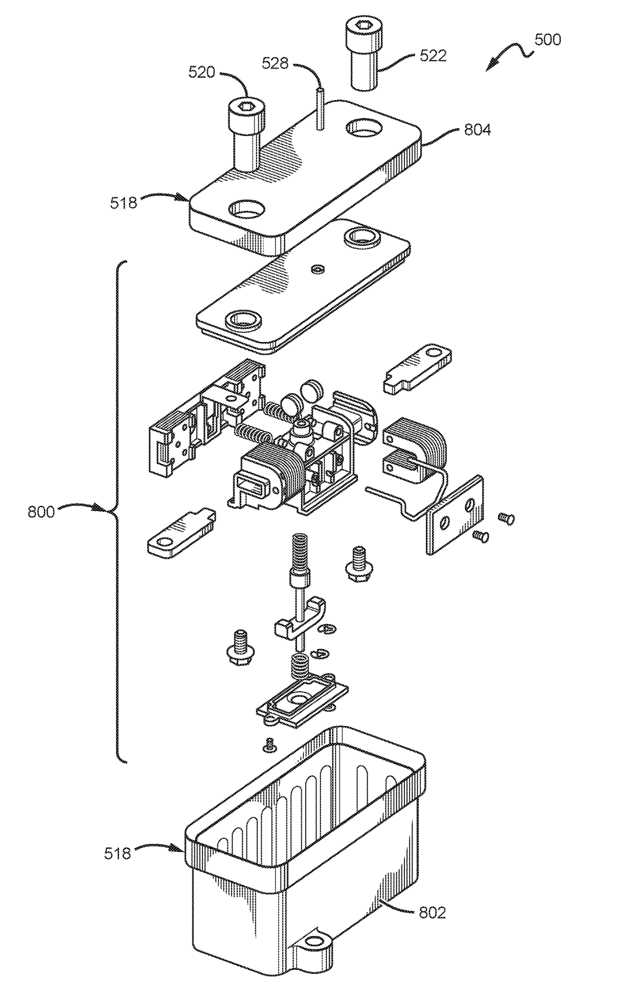
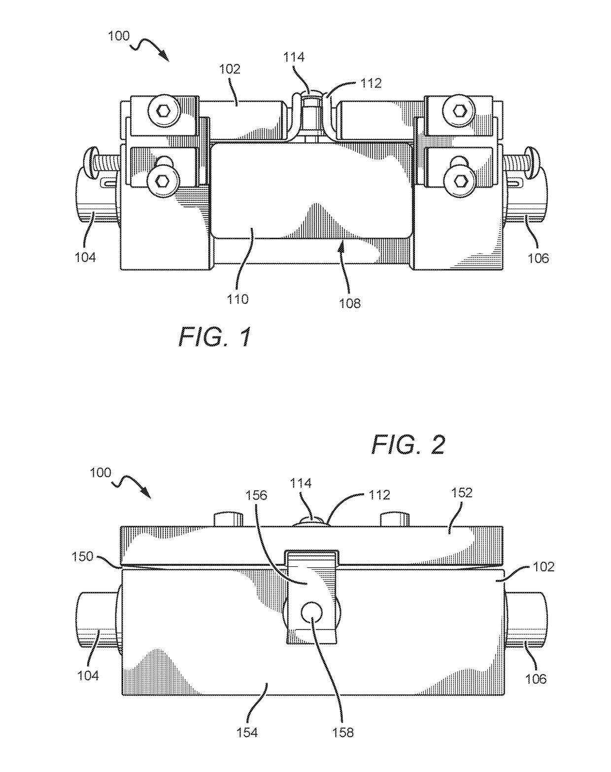
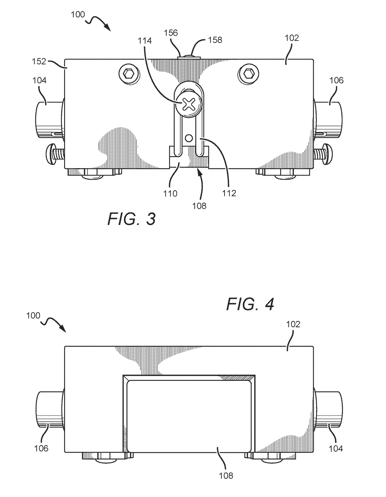
[0029]The present disclosure will now set forth detailed descriptions of various embodiments. These embodiments set forth fuse devices comprising mechanical components that are configured such that the fuse devices have triggered states (in which a circuit or other electrical flow is interrupted and the fuse is “tripped”) and non-triggered states (in which a circuit or other electrical flow is not interrupted and the fuse is “set”). In some embodiments, these mechanical components include a pin structure that is configured with one or more contacts to maintain or interrupt a circuit. In some embodiments, this pin structure is biased toward a triggered position that would break a circuit connected to the fuse device and is maintained against its bias by a mechanical pin retention structure. In some embodiments, one or more of the components of these devices are housed within a hermetically sealed portion. In some embodiments, the devices comprise a metal body at least partially surro...


PUM


Abstract

Disclosed herein are efficient mechanical fuse devices that are capable of functioning at high current levels. These devices comprise mechanical features configured such that the fuse devices have a non-triggered state, which allows current to flow through the device, and a triggered state, which does not allow current to flow through the device. In some embodiments, the devices are configured such that a certain pre-determined current level flowing through the device will generate a sufficient electromagnetic field to cause the mechanical elements to transition the fuse device into the triggered state and thus interrupt a connected electrical circuit, device or system. In some embodiments, these devices can also comprise hermetically sealed components.

Description

CROSS REFERENCE TO RELATED APPLICATIONS[0001]This application claims the benefit of U.S. Provisional Application Ser. No. 62 / 163,257 to MURRAY S. McTIGUE, et al., entitled MECHANICAL FUSE DEVICE, filed on May 18, 2015, which is hereby incorporated herein in its entirety by reference.BACKGROUND[0002]Field of the Invention[0003]Described herein are devices relating generally to fuses for use in electrical devices and systems, and specifically to fuses comprising mechanical and / or hermetically sealed features.[0004]Description of the Related Art[0005]In the field of electronics and electrical engineering, various devices can be employed in order to provide overcurrent protection, which can thus prevent short circuits, overloading, and permanent damage to an electrical system or a connected electrical device. Two of these devices include fuses and circuit breakers. A conventional fuse is a type of low resistance resistor that acts as a sacrificial device. Typical fuses comprise a metal ...

Claims


Application Information

Patent Timeline
Patent Type & Authority Patents(United States)
IPC IPC(8): H01H50/54H01H9/10H01H81/04H01H85/02H01H50/02H01H50/56H01H9/04H01H71/08H01H71/24
CPCH01H50/54H01H9/10H01H50/023H01H50/56H01H81/04H01H85/0241H01H2235/01H01H9/04H01H71/2409H01H71/2463H01H2071/088H01H2223/002H01H9/443H01H39/00H01H71/2472
Inventor MCTIGUE, MURRAY STEPHANBUSH, BERNARD VICTORHUFSTEDLER, ERIC GLENNSWARTZENTRUBER, BRENT JAMESMOLYNEUX, MICHAEL HENRYSULLIVAN, DANIEL
Owner GIGAVAC INC
Why Eureka
Try Eureka