Piezoelectric element, piezoelectric actuator and electronic instrument using the same
a piezoelectric actuator and piezoelectric technology, applied in the direction of instruments, inking apparatus, mechanical vibration separation, etc., can solve the problems of large dielectric loss at any operating temperature, insufficient piezoelectric constant, and influence on the environment, and achieve high and stable piezoelectric constant and small dielectric loss
- Summary
- Abstract
- Description
- Claims
- Application Information
AI Technical Summary
Benefits of technology
Problems solved by technology
Method used
Image
Examples
example 1
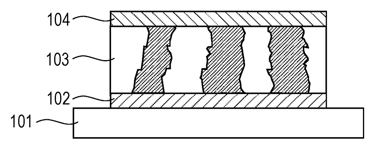
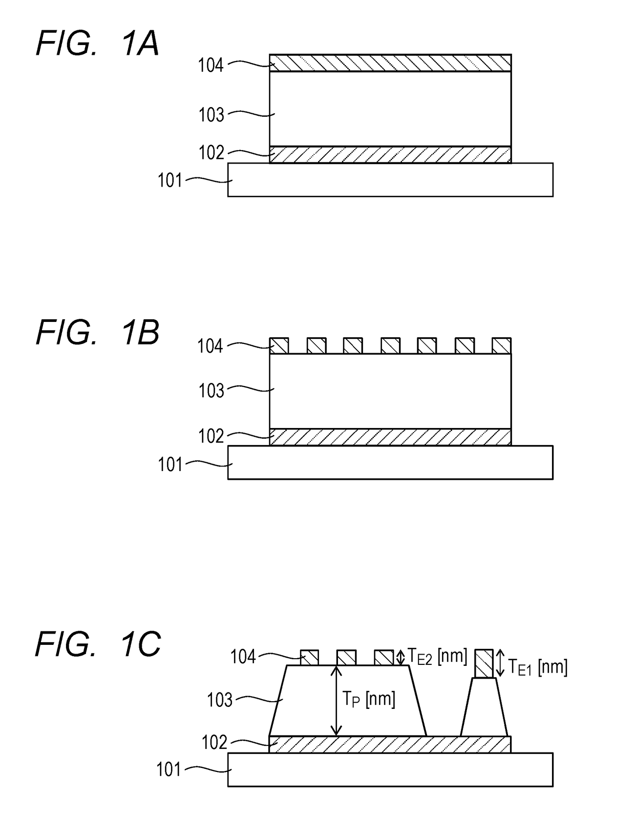
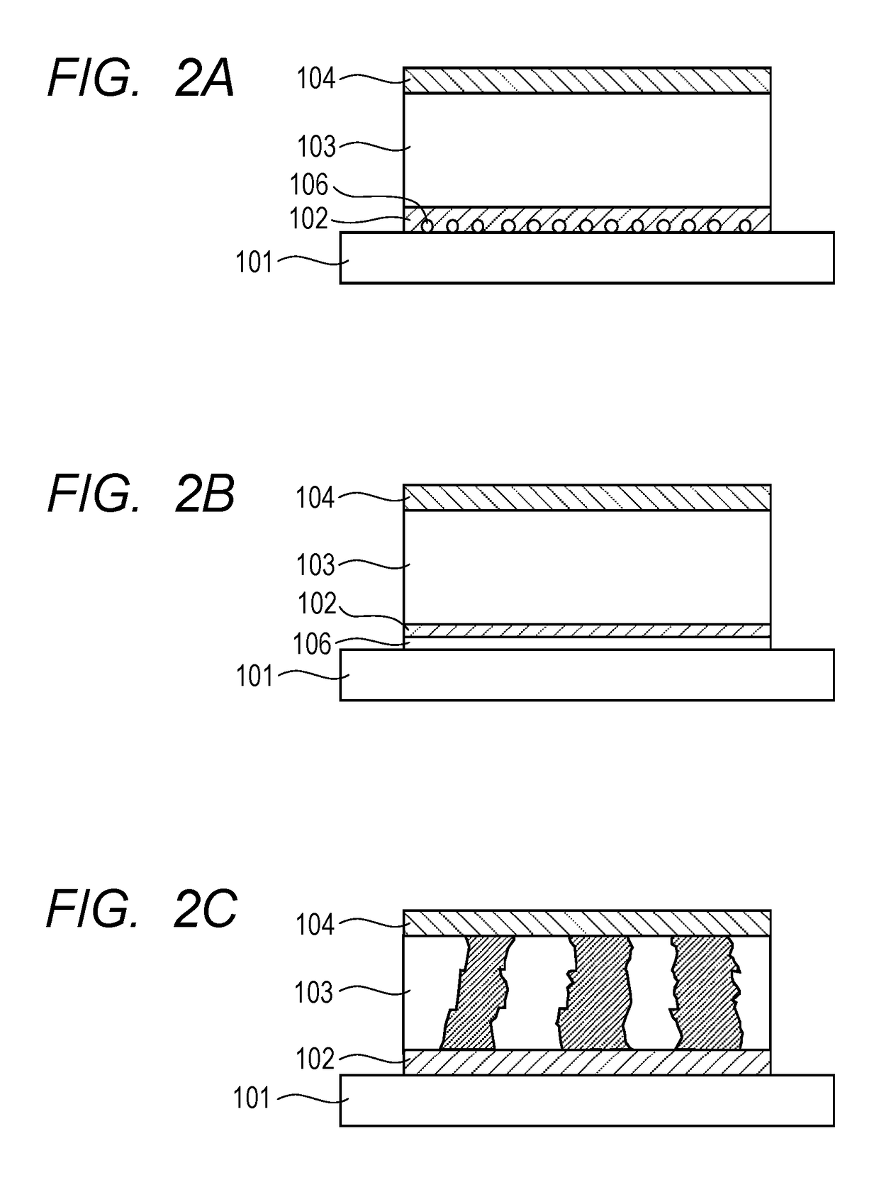
[0189]A 400 nm-thick platinum electrode was formed as the first electrode on a commercially available silicon substrate by means of DC sputtering. A titanium oxide film was formed to a thickness of 30 nm as an adhesion layer between the first electrode and the silicon substrate.
[0190]Then, a piezoelectric film containing Ba, Bi, Ti, Zr, Fe and Mn was formed on the first electrode by means of CSD.
[0191]More specifically, a piezoelectric film containing a metal oxide expressed by (Ba1-yBiy) (Ti1-x-zZrxFez)O3 of the general formula (1), where x=0.020, y=0.005 and z=0.005, or (Ba0.995Bi0.005) (Ti0.975Zr0.020Fe0.005)O3, and Mn by 0.005 mols relative to 1 mol of the metal oxide of the general formula (1) was prepared.
[0192]As the precursor liquid material to be applied by means of CSD, a liquid prepared by mixing alkoxides of the metals and dispersing them in an organic solvent was used. Ba(OC2H5)2 was used as Ba source material. Ti(OC2H5)4 was used as Ti source material. Zr(O-n-C4H9)4 wa...
example 2
[0202]The piezoelectric element of this example was prepared as in Example 1 except that RF sputtering was used instead of CSD to prepare the piezoelectric film of the piezoelectric element.
[0203]A sintered compact having a composition that corresponded to the target composition of the piezoelectric film of the piezoelectric element of this example was prepared for the purpose of using it as target of the sputtering operation. Note, however, that A-site elements such as Ba and Bi were excessively used so as to make them to be excessively found in the target of sintered compact by taking differences of evaporation speed during the film forming process using sputtering into consideration.
[0204]More specifically, the material to be used for the target that corresponds to (Ba0.995Bi0.005)1.05(Ti0.975Zr0.020Fe0.005)O3 was prepared by weighing the ingredients in a manner as described below.
[0205]Powdery reagents of barium carbonate, bismuth oxide, titanium oxide, zirconium oxide, iron oxi...
examples 3 through 25
[0209]A piezoelectric element according to the present invention was prepared in each of these examples by a method similar to those used for preparing the piezoelectric elements of Examples 1 and 2. Table 1 shows the values of x, y, z, y / z and m that evidence the compositions of the piezoelectric films of these examples. FIGS. 16A and 16B shows the relationship between the x value and the y value, the relationship between the x value and the z value and the relationship between the x value and the m value of each of the examples. The marks in FIGS. 16A and 16B indicate the composition parameter values of the examples and the dotted lines in FIGS. 16A and 16B indicate the permissible ranges of values for the purpose of the present invention. The values on the dotted lines are within the permissible ranges for the purpose of the present invention.
[0210]Table 2 shows the material of the substrate, that of the adhesion layer, the type, or the material, of the first electrode, the techn...
PUM
| Property | Measurement | Unit |
|---|---|---|
| thickness TP | aaaaa | aaaaa |
| Curie temperature | aaaaa | aaaaa |
| operating temperature | aaaaa | aaaaa |
Abstract
Description
Claims
Application Information
 - R&D
- Intellectual Property
- Life Sciences
- Materials
- Tech Scout
- Unparalleled Data Quality
- Higher Quality Content
- 60% Fewer Hallucinations
Browse by: Latest US Patents, China's latest patents, Technical Efficacy Thesaurus, Application Domain, Technology Topic, Popular Technical Reports.
© 2025 PatSnap. All rights reserved.Legal|Privacy policy|Modern Slavery Act Transparency Statement|Sitemap|About US| Contact US: help@patsnap.com


