
Piezoelectric ceramic, method for manufacturing piezoelectric ceramic, piezoelectric element, and electronic device

a piezoelectric ceramic and manufacturing method technology, applied in mechanical vibration separation, printing, vehicle components, etc., can solve the problems of low mechanical quality factor, depolarization and deterioration of piezoelectric properties, environmental impact, etc., to achieve high and stable mechanical quality factor, wide operating temperature range, and high and stable piezoelectric constant

Active Publication Date: 2015-02-26
CANON KK
View PDF4 Cites 7 Cited by
  • Summary
  • Abstract
  • Description
  • Claims
  • Application Information

AI Technical Summary

Benefits of technology

This patent describes a lead-free ceramic that can be used in a wide range of temperatures and has a stable mechanical quality factor. Its piezoelectric constant is also high, which means it can generate electricity when exposed to pressure. This invention provides a safer and more effective material for use in various applications such as ultrasonic devices and piezoelectric actuators.

Problems solved by technology

However, PZT contains lead as an A site element, and its effect on the environment is regarded as a problem.
However, these materials disadvantageously have a Curie temperature as low as 80° C. or less and therefore cause depolarization and deterioration in piezoelectric property under a high-temperature environment, such as in a car in summer.
Furthermore, these materials disadvantageously have a low mechanical quality factor and therefore tend to generate heat and, upon the application of an alternating voltage, cause depolarization.
These materials have a higher mechanical quality factor than barium titanate but disadvantageously have a poor piezoelectric property.

Method used

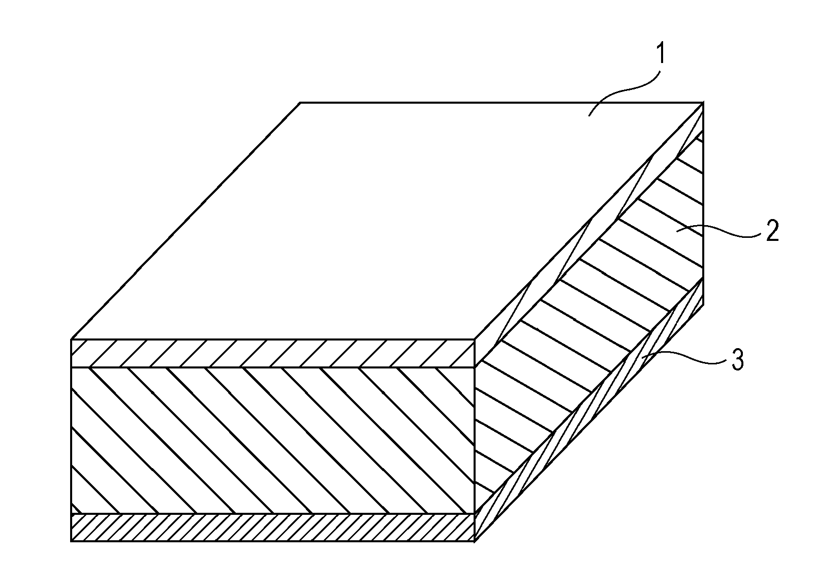
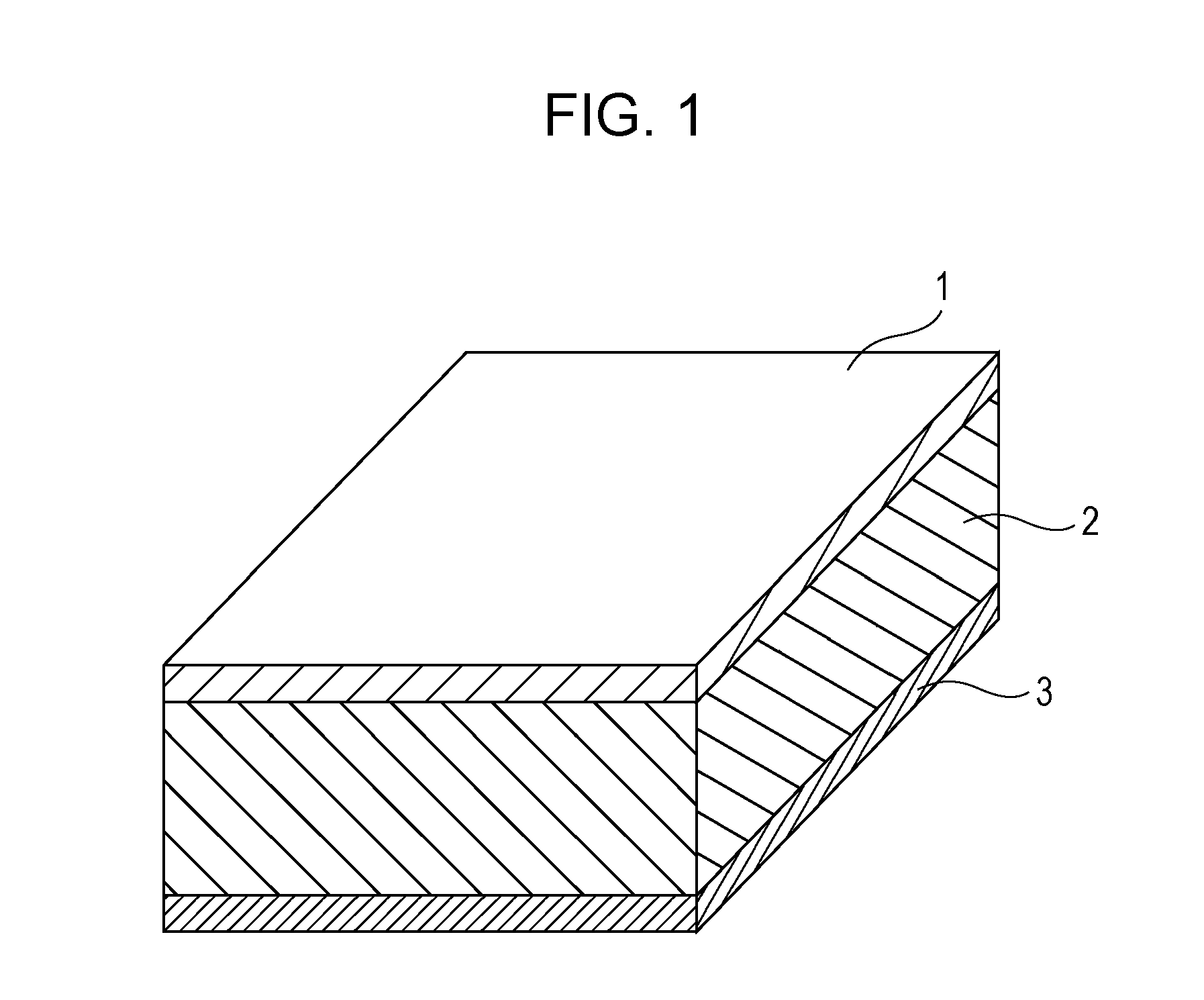
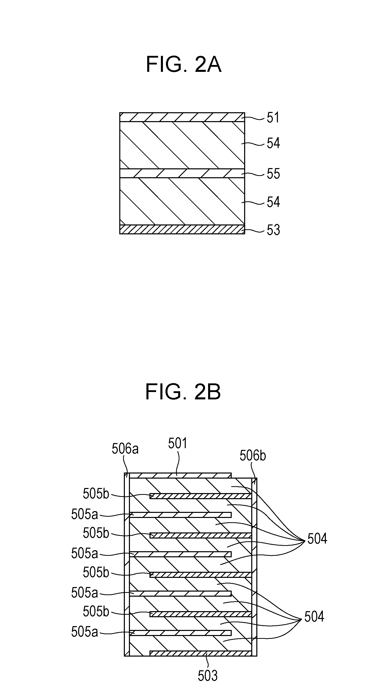

Image

  • Piezoelectric ceramic, method for manufacturing piezoelectric ceramic, piezoelectric element, and electronic device
  • Piezoelectric ceramic, method for manufacturing piezoelectric ceramic, piezoelectric element, and electronic device
  • Piezoelectric ceramic, method for manufacturing piezoelectric ceramic, piezoelectric element, and electronic device

Examples


example 1

[0182]A composition (Ba0.870Ca0.130)1.0111(Ti0.970Zr0.030)O3 was weighed as described below. This composition is represented by the general formula (Ba1-xCax)a(Ti1-yZry)O3, wherein x=0.130, y=0.030, and a=1.0111.

[0183]Barium titanate having an average particle diameter of 100 nm (BT-01, manufactured by Sakai Chemical Industry Co., Ltd.), calcium titanate having an average particle diameter of 300 nm (CT-03, manufactured by Sakai Chemical Industry Co., Ltd.), and calcium zirconate having an average particle diameter of 300 nm (CZ-03, manufactured by Sakai Chemical Industry Co., Ltd.) were weighed as the raw materials of the main component such that Ba, Ca, Ti, and Zr satisfied the composition (Ba0.870Ca0.130)1.0111(Ti0.970Zr0.030)O3. The value a representing the ratio of the number of moles of Ba and Ca at the A site to the number of moles of Ti and Zr at the B site was controlled with barium oxalate and calcium oxalate.

[0184]Manganese dioxide was weighed such that the b mol of the f...

examples 2 to 38

[0193]Piezoelectric ceramics were manufactured in the same manner as in Example 1 except that the ratio of Ba, Ca, Ti, Zr, the first auxiliary component, and the second auxiliary component and the maximum sintering temperature Tmax were changed as shown in Table 1. The raw material of Cu was copper(II) oxide.

TABLE 1FirstauxiliarySecond auxiliary componentMain componentcomponentCuSiBTotalMaximumBaCaTiZrA / BMnParts byParts by Parts byParts bytemperature1-xx1-yyaba-bweightweightweightweightTmax [° C.]Example 10.8700.1300.9700.0301.01110.01210.9990None0.01400.00660.02061200Example 20.9000.1000.9610.0391.01110.01210.9990None0.01400.00660.02061200Example 30.8700.1300.9610.0391.01110.01210.9990None0.01640.00660.02301200Example 40.8600.1400.9610.0391.01110.01210.9990None0.01870.00660.02531200Example 50.8550.1450.9610.0391.01110.01210.9990None0.01400.00660.02061200Example 60.8950.1050.9650.0351.01110.01210.9990None0.01400.00660.02061200Example 70.8600.1400.9650.0351.01110.01210.9990None0.0140...

examples 1 to 38

[0200]Piezoelectric elements were manufactured using the piezoelectric ceramics according to Examples 1 to 38.

[0201]A gold electrode having a thickness of 400 nm was formed on the front and back sides of the discoidal ceramic by DC sputtering. A titanium film having a thickness of 30 nm was formed as an adhesion layer between the electrode and the ceramic. The ceramic having the electrodes was cut into a 10 mm×2.5 mm×0.5 mm plate-like piezoelectric element.

[0202]A 1.4 kV / mm electric field was applied to the piezoelectric element on a hot plate at a temperature in the range of 60° C. to 150° C. for 30 minutes to perform polarization treatment.

[0203]The Curie temperature, the piezoelectric constant d31, and the mechanical quality factor (Qm) of each of the piezoelectric elements manufactured using piezoelectric ceramics according to examples and comparative examples of the present invention were measured after polarization treatment. Table 4 shows the results. The “phase transition po...


PUM

PropertyMeasurementUnit
equivalent circular diameteraaaaaaaaaa

Abstract

A piezoelectric ceramic contains a main component, Mn as a first auxiliary component, and a second auxiliary component containing at least one element selected from the group consisting of Cu, B, and Si. The main component contains a perovskite metal oxide having the following general formula (1):(Ba1-xCax)a(Ti1-yZry)O3(0.100≦x≦0.145,0.010≦y≦0.039)  (1)The amount b (mol) of Mn per mole of the metal oxide is in the range of 0.0048≦b≦0.0400, the second auxiliary component content on a metal basis is 0.001 parts by weight or more and 4.000 parts by weight or less per 100 parts by weight of the metal oxide, and the value a of the general formula (1) is in the range of 0.9925+b≦a≦1.0025+b.

Description

TECHNICAL FIELD[0001]The present invention relates to a piezoelectric ceramic and more particularly to a lead-free piezoelectric ceramic and a method for manufacturing the lead-free piezoelectric ceramic. The present invention also relates to a piezoelectric element, a multilayered piezoelectric element, a method for manufacturing a multilayered piezoelectric element, a liquid discharge head, a liquid discharge apparatus, an ultrasonic motor, an optical apparatus, a vibratory apparatus, a dust removing device, an image pickup apparatus, and an electronic device, each including the piezoelectric ceramic.BACKGROUND ART[0002]In general, piezoelectric ceramics are ABO3 perovskite metal oxides, such as lead zirconate titanate (hereinafter referred to as “PZT”). However, PZT contains lead as an A site element, and its effect on the environment is regarded as a problem. Thus, there is a demand for piezoelectric ceramics of lead-free perovskite metal oxides.[0003]One known piezoelectric cer...

Claims


Application Information

Patent Timeline
Patent Type & Authority Applications(United States)
IPC IPC(8): H01L41/187H01L21/64B41J2/14G02B27/00H01L41/047H01L41/083
CPCH01L41/1871H01L41/0471H01L41/083H01L41/0477B41J2202/03G02B27/0006H01L21/64B41J2002/14217B41J2/14209B06B1/06G02B7/04H02N2/106H02N2/163B41J2/14233B08B7/028C04B35/4682C04B35/6261C04B35/62695C04B35/64C04B2235/3208C04B2235/3236C04B2235/3244C04B2235/3248C04B2235/3262C04B2235/3267C04B2235/3281C04B2235/3409C04B2235/3418C04B2235/449C04B2235/5445C04B2235/5454C04B2235/6567C04B2235/77C04B2235/785C04B2235/786C04B2235/79H04N23/811H04N23/663H10N30/2047H10N30/8536H10N30/50C04B35/46C04B35/468C04B35/49H10N30/853H10N30/871H10N30/877
Inventor SAITO, HIROSHIMURAKAMI, SHUNSUKEUEDA, MIKITANAKA, HIDENORIMATSUDA, TAKANORIWATANABE, TAKAYUKIKUBOTA, MAKOTO
Owner CANON KK
Learn More