Bending stiffness reducer for brace to hull connection

a technology of reducing force and axial load bearings, which is applied in the direction of hull parts, special-purpose vessels, vessel construction, etc., can solve the problems of increasing the bending load, and affecting the bending effect so as to reduce the stiffness of the axial load bearing member and be more flexible in bending

Inactive Publication Date: 2018-02-27
COTTRELL ROY +3
View PDF11 Cites 2 Cited by
  • Summary
  • Abstract
  • Description
  • Claims
  • Application Information

AI Technical Summary

Benefits of technology

[0021]The present invention looks to reduce the rotational stiffness of the brace to hull connection, thereby reducing the induced bending moment and reducing the need for local reinforcement requirements of the connection needed to achieve the target fatigue life. By reducing the local reinforcement requirements, a reduced structural weight of the brace connection can be attained, resulting in greater Variable Deck Load capacity. The brace with reduced bending stiffness withstands the squeeze / pry loads, for which it was intended, without attracting significant bending stresses from the hull deflection, which is controlled by the deck box.
[0022]It is therefore, an objective of this invention to provide a means of connecting a brace such to reduce the bending stress at the connection.
[0023]It is therefore, an objective of this invention to provide a brace connection on a semi-submersible with improved fatigue performance by providing a means for reducing the end moment in a structural brace member, and thereby greatly reducing the bending stress at its connection.
[0024]It is therefore, an objective of this invention to provide a brace connection with less weight than a standard connection and thus provide an increased semi-submersible hull payload.
[0027]Rather than connect the brace at its end through a constant or enlarged section, reinforced to withstand induced bending, this invention reduces the stiffness of the of the axial load bearing member of the brace at that connection, resulting in an end element which is more flexible in bending.

Problems solved by technology

Due to the wave loads on the semi-submersible, significant loading of the braces can occur, particularly at their connections.
Naturally, as the brace ends are reinforced, they are stiffened, and tend to attract more bending load, caused by the hull deflection.
Reinforcing the brace to hull connection increases the rotational stiffness of the connection, attracting more load, making reinforcement an ineffective way to address the connection fatigue issues.
As a result, the brace to hull connection can be very costly to construct, requiring lots of planning, inspection and lead-time.
However, this design suffers the same cost and weight deficiencies of the 2 brace design when the one brace damaged condition is considered.
In practice, this arrangement resulted in deck box plate cracking, at the column to deck box connection, and braces were retrofitted to take the squeeze and pry loads directly, thereby reducing the deck box deflections to acceptable limits.
Other designs have added a truss-work of braces to prevent hull relative deflection and brace end relative displacement, but this results in a still heavier structural design.

Method used


Image

  • Bending stiffness reducer for brace to hull connection
  • Bending stiffness reducer for brace to hull connection
  • Bending stiffness reducer for brace to hull connection

Examples


Embodiment Construction

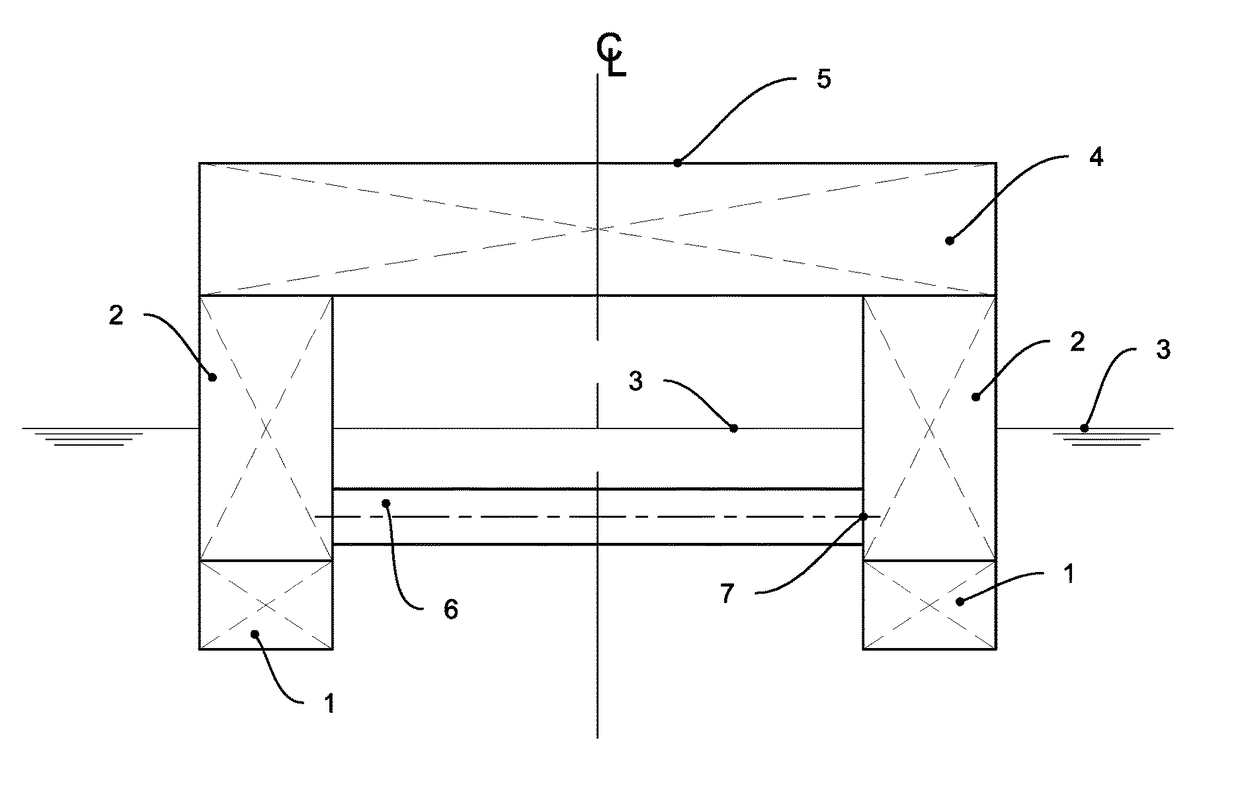
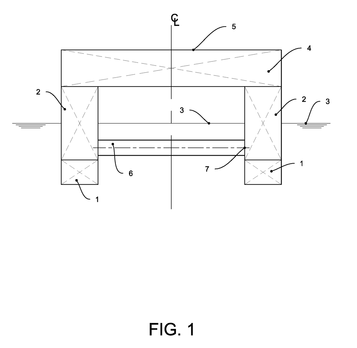
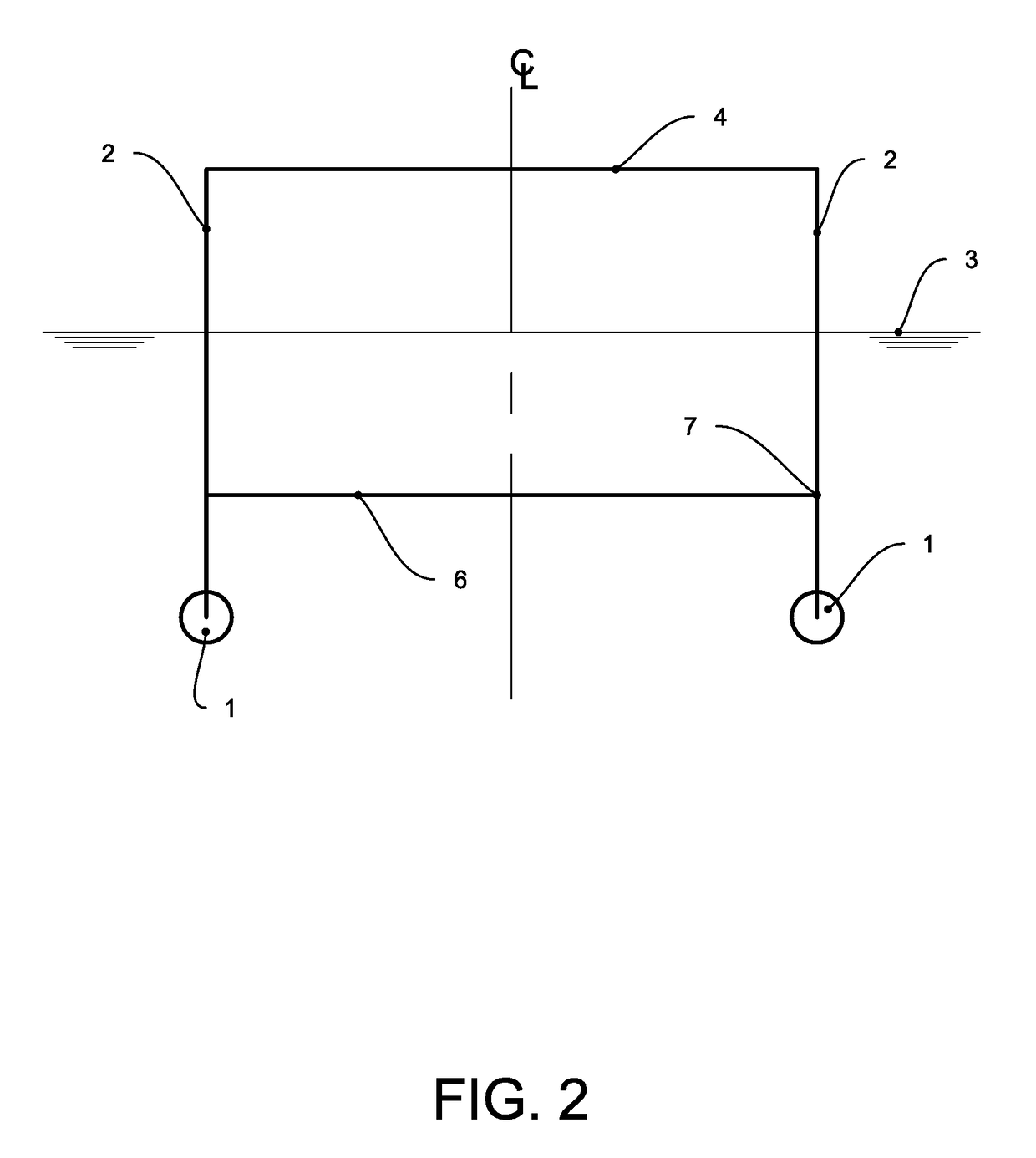
[0043]Referring now to the invention in more detail, a typical structural arrangement is shown in FIG. 1, showing a semi-submersible in section view and FIG. 2, shows a semi-submersible in section view in a diagrammatic representation. A semi-submersible, or more particularly the main hull structure of a semi-submersible is typically composed of a series of pontoons 1, columns 2, and an upper box structure 4. The hull of the semi-submersible is buoyant, operating at a waterline 3 approximately as indicated. The main deck 5 structure varies in its arrangement depending upon the intended use of the semi-submersible such as drilling, oil production, construction support, accommodations, etc. The brace structure 6 is shown, in this case, the standard way with built-in, or fixed ends 7.

[0044]For better understanding, FIG. 3 shows a semi-submersible in profile view, showing the same elements as in the section view, pontoons 1, columns 2, operating waterline 3, deck box 4, main deck 5 and ...


PUM


Abstract

Semi-submersibles are subjected to loading from waves, causing racking, longitudinal shear and parallelogramming, or differential movement of the pontoons. The cyclic wave loading makes the various connections, where stress concentrations occur, susceptible to fatigue damage throughout the hull structure. This is most evident at the connections between the braces and the main hull structure. A revised brace to main hull connection with reduced bending stiffness is employed to reduce the moment being transferred from the brace to the hull, thereby reducing the bending stress and susceptibility to fatigue damage. This improved connection employs an internal member to transfer the loads between the brace and hull structure mainly as tension and compression. As a consequence of the improved fatigue performance, the structural weight of the connection can be greatly reduced, thus increasing the capacity with which the semi-submersible hull can operate.

Description

CROSS-REFERENCE TO RELATED APPLICATIONS[0001]This application is a Non-Provisional Application claiming priority to U.S. Provisional Patent Application No. 62 / 302,905, entitled “Bending Stiffness Reducer for Brace to Hull Connection,” filed Mar. 3, 2016, which is herein incorporated by reference.STATEMENT REGARDING FEDERALLY SPONSORED RESEARCH OR DEVELOPMENT[0002]This invention was not made under federally sponsored research or development.REFERENCE TO SEQUENCE LISTING, A TABLE, OR A COMPUTER PROGRAM LISTING COMPACT DISC APPENDIX (IF APPLICABLE)[0003]This is not applicable.BACKGROUND OF THE INVENTION[0004]This invention relates to mobile offshore units. Mobile offshore units are used in the offshore industry mainly for drilling and production operations, but also for general construction operations, crew accommodation, wind-turbine installation, etc. Semi-submersibles are a type of floating mobile offshore unit designed to provide a stable platform to support the necessary offshore ...

Claims


Application Information

Patent Timeline
Patent Type & Authority Patents(United States)
IPC IPC(8): B63B35/44B63B1/12B63B3/14B63B1/10
CPCB63B1/121B63B1/107B63B35/44B63B3/14B63B2035/448B63B35/4413B63B3/26B63B3/70B63B2003/145
Inventor COTTRELL, ROYGRASSO, BARTONSTRACHAN, FRANKVAZQUEZ, JOSE H.
Owner COTTRELL ROY
Why Eureka
Try Eureka