Vehicle cooling device

a cooling device and vehicle technology, applied in the direction of liquid fuel engines, machines/engines, machines/engines, etc., can solve the problems of affecting the driving of the vehicle, the inability to appropriately deal with the large affecting of cooling efficiency of static electricity charged to the radiator or the condenser, so as to improve the cooling efficiency and affect the cooling efficiency

Active Publication Date: 2018-02-27
TOYOTA JIDOSHA KK
View PDF59 Cites 2 Cited by
  • Summary
  • Abstract
  • Description
  • Claims
  • Application Information

AI Technical Summary

Benefits of technology

[0007]The inventors paid attention especially to a radiator, a condenser, and a fan cover including a fan for cooling the radiator and the condenser, and studied an influence of static electricity charged to the radiator or the condenser on driving of a vehicle. As a result of the study, the inventors found that static electricity charged to the radiator or the condenser greatly affects cooling efficiency. Then, based on this discovery, the inventors found an adequate static elimination method required for improving cooling efficiency.
[0010]According to this aspect of the invention, by installing the self-discharge static eliminator on the non-conductive wall surface of the connecting part that connects the radiator or the condenser with the fan cover, static elimination of the radiator or the condenser is performed, thereby improving cooling efficiency.

Problems solved by technology

However, it is not clearly known why and how the static electricity charged to a vehicle affects driving of the vehicle.
However, without knowing why and how static electricity charged to a vehicle affects driving of the vehicle, it is not possible to appropriately deal with static electricity charged to a vehicle.
As a result of the study, the inventors found that static electricity charged to the radiator or the condenser greatly affects cooling efficiency.

Method used


Image

  • Vehicle cooling device
  • Vehicle cooling device
  • Vehicle cooling device

Examples


Embodiment Construction

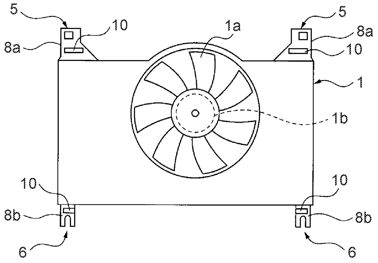
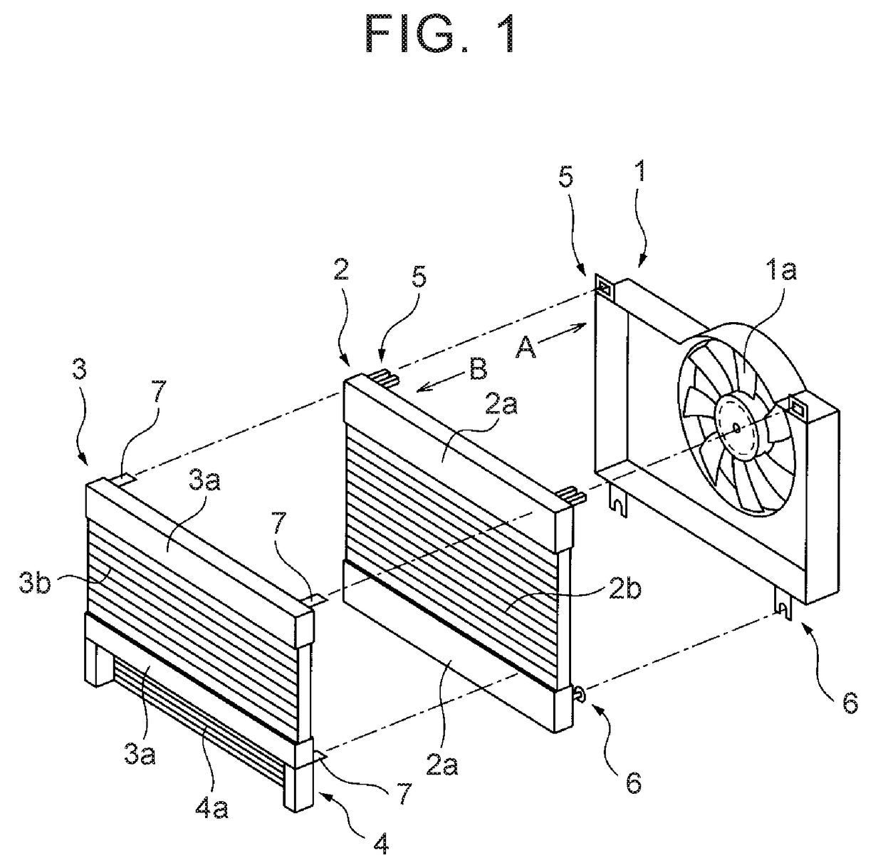
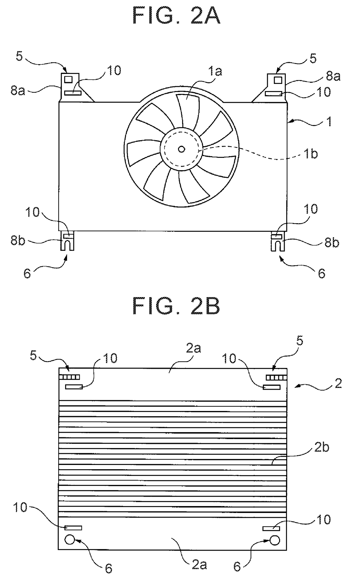
[0029]Herein below, an embodiment of the invention is explained with reference to FIG. 1 to FIG. 9B. FIG. 1 shows an exploded perspective view showing an illustration of a vehicle cooling device including a fan cover 1, a radiator 2, and a condenser 3. With reference to FIG. 1, a fan 1a and an electric motor 1b (FIG. 2A) for driving the fan 1a are mounted on the fan cover 1. Although an actual structure of the fan cover 1 is complex, the fan cover 1 shown in FIG. 1 is extremely simplified. In the embodiment shown in FIG. 1, the fan cover 1 is made of a non-conductive synthetic resin material.

[0030]Meanwhile, the radiator 2 shown in FIG. 1 is a radiator including cooling water for an engine. In the embodiment shown in FIG. 1, the radiator 2 includes upper and lower tanks 2a, and a core 2b arranged between the upper and lower tanks 2a. In the embodiment shown in FIG. 1, the upper and lower tanks 2a are made of a non-conductive synthetic resin material, and the core 2b is made of a met...


PUM


Abstract

A vehicle cooling device includes: at least one of a radiator and a condenser; a fan cover including a fan configured to cool the at least one of the radiator and the condenser, the radiator, the condenser and the fan cover being positively charged; a connecting part that connects the at least one of the radiator and the condenser and the fan cover with each other; and a self-discharge static eliminator that is installed on a non-conductive wall surface of the connecting part, and is configured to decrease an electric charge amount of a part of the non-conductive wall surface within a limited range, centered on a location where the self-discharge static eliminator is installed, static elimination of the at least one of the radiator and the condenser being performed by the self-discharge static eliminator.

Description

INCORPORATION BY REFERENCE[0001]The disclosure of Japanese Patent Application No. 2014-257972 filed on Dec. 19, 2014 including the specification, drawings and abstract is incorporated herein by reference in its entirety.BACKGROUND OF THE INVENTION[0002]1. Field of the Invention[0003]Embodiments of the present invention relate to a vehicle cooling device.[0004]2. Description of Related Art[0005]A vehicle is publicly known, in which a discharge device such as a discharge antenna is mounted on an engine or an engine-related member of the vehicle, and high-voltage electricity, static electricity and so on generated and charged in the engine area is discharged and emitted outside, thereby improving fuel economy (for example, see Japanese Patent Application Publication No. 5-238438 (JP 5-238438 A)).[0006]As described in JP 5-238438 A, it is known that static electricity is charged to a vehicle, and that static electricity charged to a vehicle has some kind of influence on driving of the v...

Claims


Application Information

Patent Timeline
Patent Type & Authority Patents(United States)
IPC IPC(8): F01P11/02F01P9/00B60K11/04F01P11/14F01P11/04F01P3/20F02B63/04F01P5/06
CPCF01P11/14B60K11/04F01P9/00F02B63/04F01P5/06F01P11/02F01P11/04F01P3/20B60K11/00F01P11/00F04D29/023H05F3/00F01P3/18H05F3/04H01T19/00B60R16/06
Inventor TANAHASHI, TOSHIOKANEHARA, YOJIYAMADA, KOSHI
Owner TOYOTA JIDOSHA KK
Why Eureka
Try Eureka