Digital driving of active matrix displays
a display and active matrix technology, applied in the field of digital driving of active matrix displays, can solve the problems of limiting accuracy, non-linear display response, and sensitive display to nois
- Summary
- Abstract
- Description
- Claims
- Application Information
AI Technical Summary
Benefits of technology
Problems solved by technology
Method used
Image
Examples
example 1
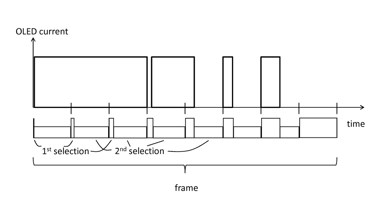
[0060]In case the number of bits n is 5 and N=n, N=5. Additionally, in this example, the sub-frames are chosen to have substantially the same duration. Further, the first selection may introduce data corresponding to intensity values of images to be represented, and the second selection may introduce a logical 0, turning the corresponding pixel OFF. In this particular embodiment, an image frame (with a frame duration of fp) will be divided in 5 sub-frames of equal length. In the first sub-frame, there will be a first selection during which data (logical 1 or logical 0) corresponding to the value of the LSB is shown by the display pixel. This takes place during ½5−1= 1 / 16 of the sub-frame duration, and then the second selection during this first sub-frame turns the pixel OFF (logical 0). The second sub-frame will have the second LSB introduced and being displayed during ½5−2=⅛ of the sub-frame duration, the pixel being OFF the rest of the sub-frame. The process repeats until the last...
example 2
[0072]In one embodiment (further illustrated in FIG. 6 and FIG. 7), after selection of a row by the first select signal, a digital code corresponding to a bit of the digital image code is written to the corresponding pixels of that row. For example, upon selection of a row by the first running one a pixel is switched ON if the corresponding data bit is a logical 1. The pixel remains switched OFF if the corresponding data bit is a logical 0. The second select signal switches the pixel OFF.
[0073]In one embodiment, as illustrated in FIG. 6, the data code is an n-bit code representing pixel intensity data representing the image, for instance 8-bit code. Each frame may be divided in N=n sub-frames, in the case illustrated 8 sub-frames. The method starts with a first sub-frame displaying, upon the first select signal going high, the least significant bit of the 8 bit (n bit) digital representation of an image frame. If the select signals are running ones, the present invention not being l...
example 3
[0076]In another embodiment of a method according to an aspect of the present invention, the duty cycle can be substantially increased, to almost 100%. It is to be noted that, for the case illustrated with an 8-bit data code, applying the alternative embodiment in which N equals the (superior) closest power of 2 is trivial, because 8 is a power of 2, so N also equals 8 and the frame will be divided in 8 sub-frames. For example, for an n (8) bit display each sub-frame can be divided into 2n / N (28 / 8=32) time slots, resulting in a total of 2n (28=256) time slots per frame period. The LSB is assigned to one time slot, the second LSB is assigned to 2 time slots, the next bit is assigned to 4 time slots, and so on, doubling the number of time slots for every next more significant bit. The MSB is assigned to 2n−1 time slots (in case of 8 bits, 128 time slots). As compared to the embodiments described above, within the OFF time of lower significant bits, rather than completely switching OFF...
PUM
| Property | Measurement | Unit |
|---|---|---|
| time delay | aaaaa | aaaaa |
| voltage drop | aaaaa | aaaaa |
| power | aaaaa | aaaaa |
Abstract
Description
Claims
Application Information
 - R&D
- Intellectual Property
- Life Sciences
- Materials
- Tech Scout
- Unparalleled Data Quality
- Higher Quality Content
- 60% Fewer Hallucinations
Browse by: Latest US Patents, China's latest patents, Technical Efficacy Thesaurus, Application Domain, Technology Topic, Popular Technical Reports.
© 2025 PatSnap. All rights reserved.Legal|Privacy policy|Modern Slavery Act Transparency Statement|Sitemap|About US| Contact US: help@patsnap.com


