Radiation detector

Active Publication Date: 2018-03-06
SHIMADZU CORP
View PDF15 Cites 9 Cited by
  • Summary
  • Abstract
  • Description
  • Claims
  • Application Information

AI Technical Summary

Benefits of technology

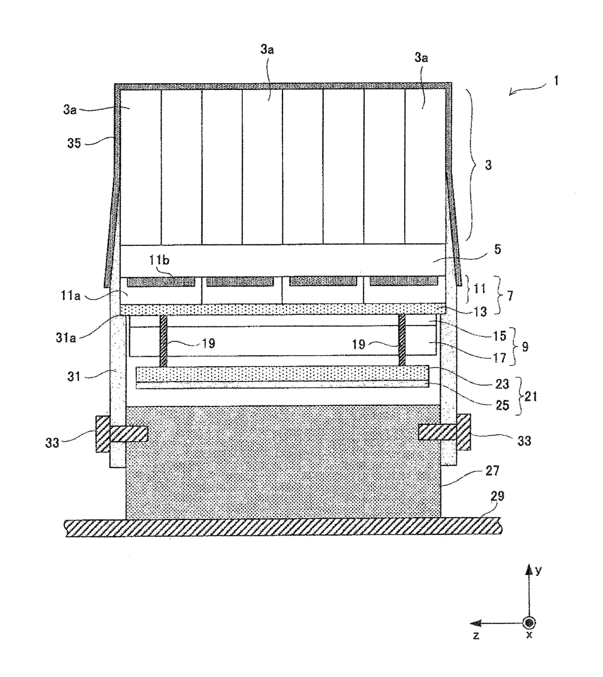
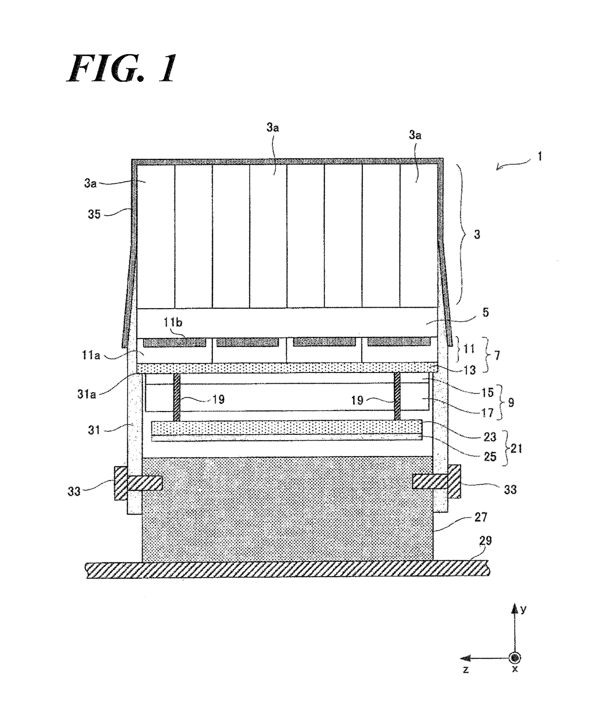
[0061]Specifically, a radiation detector of the present invention comprises the holding member and the light shielding member. The holder member that are installed to the respective side-peripheries of the light detector, the light guide, and the scintillator block comprises connection members and base fastening members. The connection members connect and hold the side-periphery of the light detector and the bottom, so that a location shift of the light detector can be adequately and effectively prevented. The light detector photochemically connects the scintillator block and the light guide, so that the location shift of the scintillator block can be adequately and effectively prevented by the holding members.
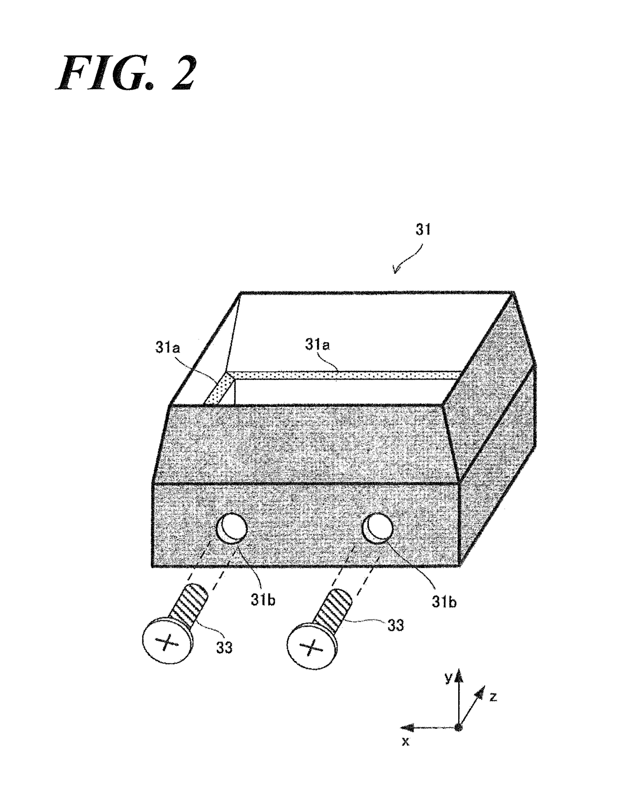
[0062]The holding members are fastened with the base elements installed to the location sandwiching the light detector and facing the scintillator lights through the base fastening member. In such case, the design of the base fastening member is facilitated to fasten the base members and the holding members more strongly. The base members and the holding members are fastened strongly, so that the holding member can hold more stably the light detectors. Accordingly, the fastening strength of the radiation detectors can be much stronger.
[0063]The light shielding member having the adhesive property covers the outer-periphery of the scintillator block and the side-periphery o

Problems solved by technology

Nevertheless, in the case of a conventional example having such structure, following problems are remained to be solved.
Firstly,

Method used


Image

  • Radiation detector
  • Radiation detector
  • Radiation detector

Examples


Embodiment Construction

[0081]Reference will now be made in detail to embodiments of the invention. Wherever possible, same or similar reference numerals are used in the drawings and the description to refer to the same or like parts or steps. The drawings are in simplified form and are not to precise scale. The word ‘couple’ and similar terms do not necessarily denote direct and immediate connections, but also include connections through intermediate elements or devices. For purposes of convenience and clarity only, directional (up / down, etc.) or motional (forward / back, etc.) terms may be used with respect to the drawings. These and similar directional terms should not be construed to limit the scope in any manner. It will also be understood that other embodiments may be utilized without departing from the scope of the present invention, and that the detailed description is not to be taken in a limiting sense, and that elements may be differently positioned, or otherwise noted as in the appended claims wi...


PUM


Abstract

A radiation detector for a PET-MR apparatus, has a fastening-strength and a high cooling efficiency relative to a photoelectric conversion element. A holding member 31 holds a side-periphery and a bottom of a light detector 7 by a connection element 31a, and is strongly fastened by a connection base 27 and a gimlet hole 31b and a screw 33. A light shielding film 35 is a thin-film and adheres and covers an outer-periphery and the side-periphery of the holding member 31. The radiation detector has a robust fastening-strength, so that a locational shift of the scintillator block 3 is prevented. As a result, the radiation detector can detect γ-ray data accurately.

Description

CROSS REFERENCE TO RELATED APPLICATIONS[0001]This application relates to, but does not claim priority from, JP 2014-215290 filed Oct. 22, 2014, the entire contents of which are incorporated herein by reference.FIGURE SELECTED FOR PUBLICATION[0002]FIG. 1BACKGROUND OF THE INVENTIONField of the Invention[0003]The present invention relates to a radiation detector applied to a combined apparatus for positron emission tomography and magnetic resonance tomography to obtain a nuclear medicine image and a magnetic resonance image at the same time.Description of the Related Art[0004]Conventionally, a positron emission tomography (PET) is known as a medical imaging. Positron emission tomography apparatus, i.e., PET apparatus is an apparatus that generates PET image showing distribution of radiopharmaceuticals labeled with a positron-emitting radionuclide inside a subject.[0005]A PET apparatus comprises multiple radiation detectors arranged as circularly surrounding a subject. The radiopharmace...

Claims


Application Information

Patent Timeline
IPC IPC(8): G01T1/20G01R33/48G01T1/29G01T1/16
CPCG01T1/1603G01R33/481G01T1/2018G01T1/2002G01T1/2985G01T1/20G01T1/20185G01T1/20188
Inventor TONAMI, HIROMICHIFURUTA, MASAFUMI
Owner SHIMADZU CORP
Why Eureka
Try Eureka