
Electric energy harvester for display panel

a technology of display panel and electric energy harvester, which is applied in the direction of greenhouse gas reduction, device material selection, identification means, etc., can solve the problems of reducing the efficiency of solar cells, limiting the volume of batteries, and reducing the portability and ease of use of devices, so as to improve battery efficiency and generate electric energy continuously, the effect of improving the efficiency of batteries

Active Publication Date: 2018-03-06
RES & BUSINESS FOUND SUNGKYUNKWAN UNIV
View PDF5 Cites 0 Cited by
  • Summary
  • Abstract
  • Description
  • Claims
  • Application Information

AI Technical Summary

Benefits of technology

This solution enables continuous energy supply to display panels, enhances energy generation efficiency, and allows for energy harvesting in various environments, including low-light conditions, by combining piezoelectric and solar cell technologies, while maintaining a slim and portable form factor.

Problems solved by technology

However, the bulkiness may reduce the portability and ease of use of the devices.
Thus, there is a limit to increase the volume of the battery, so that a new alternative capable of supplying electricity to the electronic devices using the display is required.
For example, solar cells in conventional solar-based displays are not transparent and thus have a problem in that they are very inefficient due lower energy generation since the solar cells are the side or back of the display.
In addition, when the weather is cloudy or rainy, the efficiency of the solar cell is rapidly lowered.
Therefore, there is a problem that the solar cell is less commercialized because it generates less electric energy compared to the facility cost.

Method used


Image

  • Electric energy harvester for display panel
  • Electric energy harvester for display panel
  • Electric energy harvester for display panel

Examples


example

[0056]A piezoelectric layer containing therein reflective particles is prepared. Hereinafter, this piezoelectric layer containing therein reflective particles is referred to as a “light guide layer”. As for the light guide layer, the reflective particles are made of quantum dots (QDs) and the piezoelectric layer material is selected as a P(VDF-TrFE)(poly(vinylidenefluoride-co-trifluoroethylene).

[0057]The light guide layer is measured in terms of optical properties. The results thereof are shown in FIG. 4A-4C. In this measurement, a light beam having 300-800 nm wavelength is irradiated to the light guide layer using Shimadzu UV-VIS-NIR UV-3600. As shown FIG. 4A-4C, as a concentration of quantum dots increases, emission and transmittance of the light beams decrease for specific wavelengths. FIG. 4A shows that quantum dots (CdSe / ZnS core / shell structures) are good at absorbing the light beams having wavelengths (UV light) smaller than or equal to 400 nm, and, thus, the absorbance for t...


PUM


Abstract

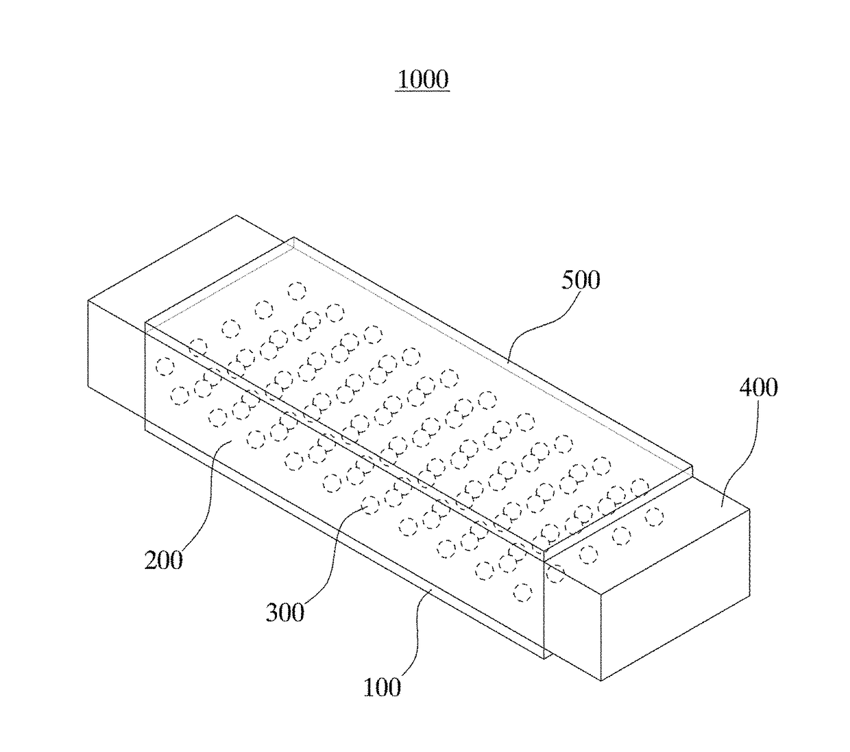
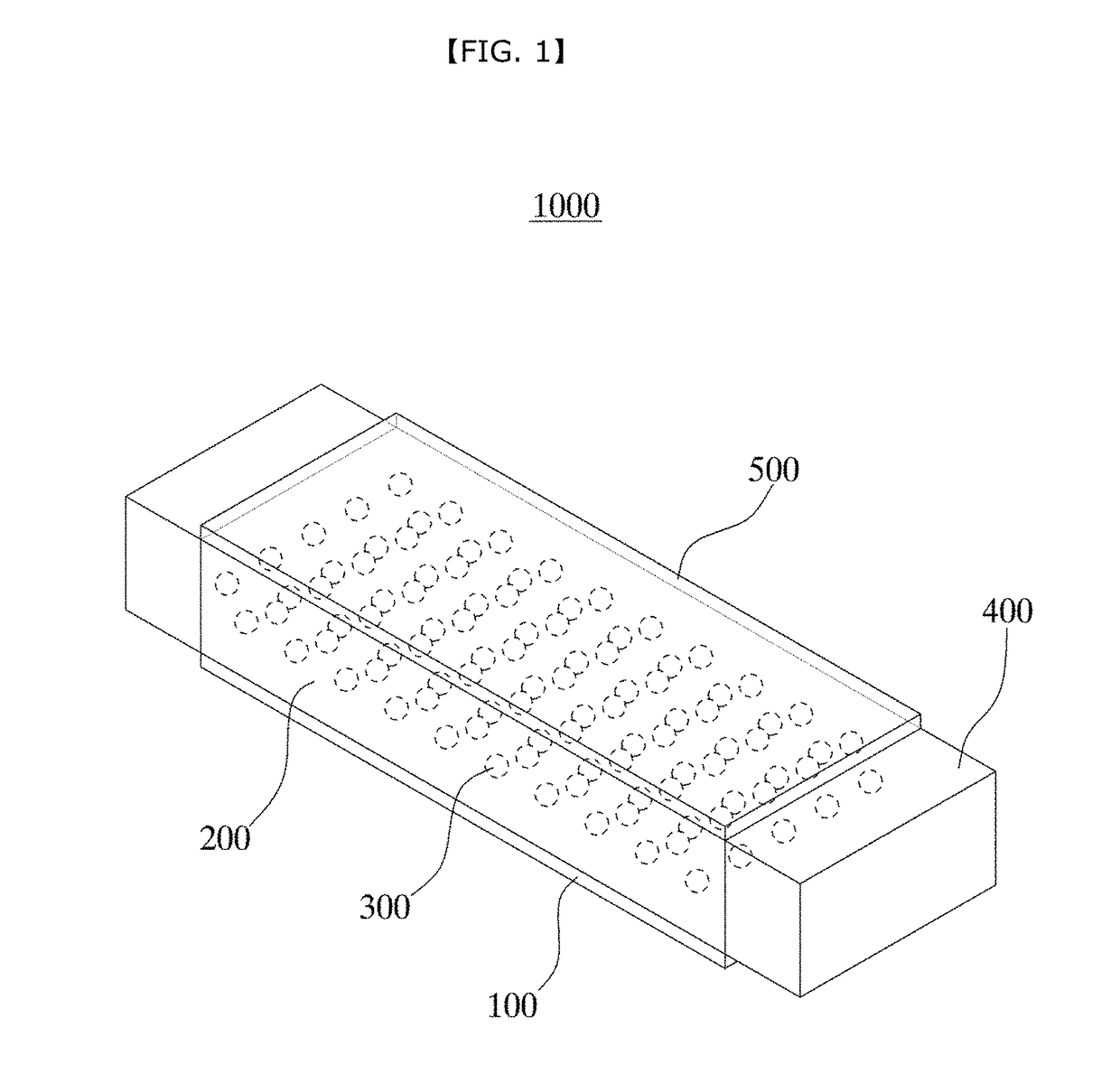
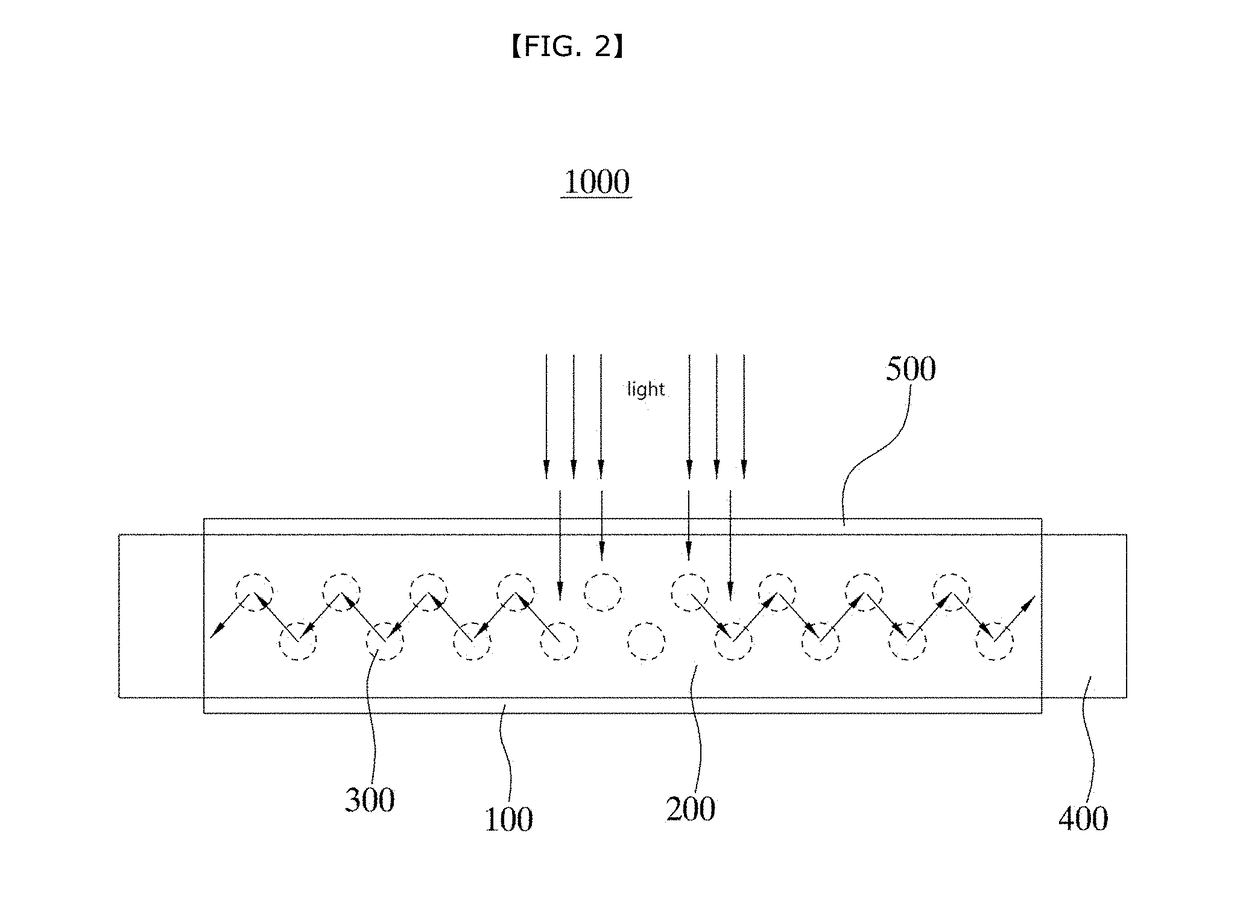
There is provided an electrical-energy harvester for a display panel, the harvester comprising: a transparent and flexible lower electrode; a transparent and flexible piezoelectric layer on the lower electrode; reflective particles dispersed in the piezoelectric layer for reflecting light beams incident into the piezoelectric layer; a transparent and flexible upper electrode on the piezoelectric layer, wherein the upper and lower electrodes are opposite to each other; and at least one solar cell disposed on at least one lateral side of the piezoelectric layer, wherein at least one solar cell is configured to receive the light beam reflected from the reflective particles and, thus, to generate electrical energy.

Description

CROSS-REFERENCE TO RELATED APPLICATION[0001]This application claims the benefit of Korea patent application No. 10-2015-0178943 filed on Dec. 15, 2015, the entire content of which is incorporated herein by reference for all purposes as if fully set forth herein.BACKGROUND[0002]Field of the Present Disclosure[0003]The present disclosure relates to an electrical energy harvester, and, more particularly, to an electrical-energy harvester for a display panel wherein the harvester is disposed on the display panel surface and is flexible and transparent and is configured to generate electrical energy upon receipt of optical energy and / or physical force.[0004]Discussion of Related Art[0005]As electronic devices using displays are becoming commonplace and technologies thereof are developed, the thickness of electronic devices is thinned, the resolution of displays is improved, and the amount of electric energy consumed is increasing. In this connection, the proportion of the volume occupied...

Claims


Application Information

Patent Timeline
Patent Type & Authority Patents(United States)
IPC IPC(8): H01L31/044H01L31/054H02S10/10H01L41/113H01L41/18H10N30/00H10N30/30H10N30/85
CPCH01L31/0547H01L41/113H02S10/10H01L41/183Y02E10/52Y02E70/30H10N30/30H10N30/852H02S40/22H02S40/38G09F9/30H02N2/18H02N11/002Y02E10/50
Inventor KIM, SANG WOOLEE, KANG HYUCKPARK, HEY JUNGKIM, SUNG KYUNKIM, TAE YUNYOON, HONG JOON
Owner RES & BUSINESS FOUND SUNGKYUNKWAN UNIV
Learn More