

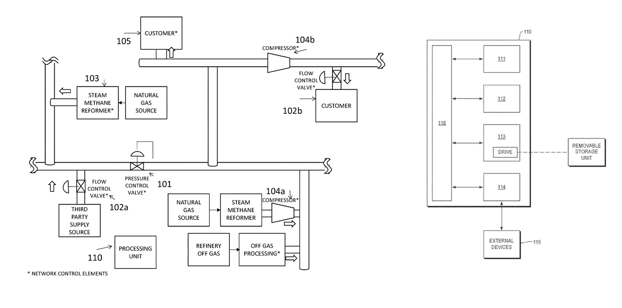
Control system in a gas pipeline network to satisfy demand constraints
a technology of control system and gas pipeline network, which is applied in the direction of process and machine control, mechanical equipment, instruments, etc., can solve the problems of reducing the practical application, limiting the effective scaling of gas pipeline networks, and constructing efficient mixed-integer linear program formulations, so as to reduce effectively scale, and the effect of reducing the complexity of optimization problems
- Summary
- Abstract
- Description
- Claims
- Application Information
AI Technical Summary
Benefits of technology
Problems solved by technology
Method used
Image

Examples
example 1
[0208]This example is small enough that extensive detail can be provided. In this example, there are three customers and three plants. In the network diagram of FIG. 12, customers are represented as squares and plants are represented as double circles.
[0209]Parameters for each of the eight nodes in the network are shown in Table 1. For the customer demand nodes, the minimum acceptable pressure is 2 Pa (corresponding to a squared pressure of 4 Pa2). For the plant supply nodes, the maximum acceptable pressure is 5 Pa (corresponding to a squared pressure of 25 Pa2). The table shows that the lower and upper bounds demand for the customer at node 1 are 0.349 and 0.399 kg / s, respectively; the lower and upper bounds demand for the customer at node 4 are 0.108 and 0.208 kg / s, respectively; and the lower and upper bounds demand for the customer at node 4 are 0.863 and 1.063 kg / s, respectively. The table also shows that the gas production plant located at node 3 can range from 0 to 0.597 kg / s...
PUM
 Abstract
Description
Claims
Application Information