Apparatus of plural charged-particle beams

a technology of charged particles and apparatuses, applied in electrical apparatuses, electric discharge tubes, basic electric elements, etc., can solve the problems of reducing the yield to a great degree, reducing the capacity of conventional yield management tools with optical beams, and not providing throughputs competent for mass production, etc., to reduce the strong coulomb effect, the effect of high throughput and high resolution

Active Publication Date: 2018-03-20
ASML NETHERLANDS BV
View PDF6 Cites 39 Cited by
  • Summary
  • Abstract
  • Description
  • Claims
  • Application Information

AI Technical Summary

Benefits of technology

[0017]The object of this invention is to provide a new multi-beam apparatus which provide both high resolution and high throughput for observing a sample in flexibly varying observing conditions (such as currents and landing energies of the probe spots, electrostatic field on the sample surface). The apparatus can function as a yield management tool to inspect and / or review defects on wafers / masks in semiconductor manufacturing industry. At first, the new multi-beam apparatus uses a movable collimating lens to vary the currents of the plurality of probe spots without incurring pitch variations thereof. Secondly, the new multi-beam apparatus employs a new source-conversion unit to form the plurality of parallel real images of the single electron source and compensate off-axis aberrations of the plurality of probe spots with respect to the currents and the landing energies thereof. Furthermore, a pre-beamlet-forming means is placed close to the single electron source to reduce the strong Coulomb effect due to the primary-electron beam as soon as possible.
[0027]The present invention also provides a method to configure a source-conversion unit in a multi-beam apparatus for observing a surface of a sample, which comprises steps of providing a beamlet-forming means with a plurality of beam-limit openings, providing an image-forming means with a plurality of electron optics elements, providing one or more micro-multipole-lenses in each of the plurality of electron optics elements, and enabling that one or more micro-multipole-lenses to generate a round-lens field, a dipole field and a quadrupole field for compensating field curvature, distortion and astigmatism of one corresponding probe spot of the apparatus.
[0028]The present invention also provides a method to reduce Coulomb effect in a multi-beam apparatus for observing a surface of a sample, which comprises steps of placing a pre-beamlet-forming means between an electron source and a source-conversion unit of said apparatus. The pre-beamlet-forming means has a plurality of beamlet-forming apertures which divide a primary-electron beam of the electron source into a plurality of beamlets. A plurality of beam-limit openings of the source-conversion unit limits currents of the plurality of beamlets.
[0032]The present invention also provides a device for providing multiple sources, which comprises a charged-particle source for providing a primary beam along an optical axis of the device, a lens for condensing the primary beam along the optical axis, a plate including a plurality of openings for trimming the primary beam into a plurality of beamlets, and a plurality of micro-multipole-lens for respectively focusing the plurality of beamlets to form a plurality of images of the charged-particle source, and providing a plurality of dipole fields and quadrupole fields individually, wherein the plurality of images becomes the multiple sources which emit the plurality of beamlets respectively. The plurality of dipole fields, in the embodiment, can preserve or keep positions of the plurality of images or sources.

Problems solved by technology

For manufacturing semiconductor IC chips, pattern defects and / or uninvited particles (residuals) inevitably appear on a wafer and / or a mask during fabrication processes, which reduce the yield to a great degree.
Accordingly, the conventional yield management tools with optical beam gradually become incompetent due to diffraction effect, and yield management tools with electron beam are more and more employed.
Currently, the yield management tools with electron beam employ the principle of scanning electron microscope (SEM) with a single electron beam, which therefore can provide higher resolution but can not provide throughputs competent for mass production.
Although a higher and higher current of the single electron beam can be used to increase the throughputs, the superior spatial resolutions will be fundamentally deteriorated by the Coulomb Effect which increases with the beam current.
Two key issues limit the available performance and application conditions (currents and landing energies of the plural beamlets) of this multi-beam apparatus as one yield management tool.
The first one is the difficulty of changing currents of the plural beamlets or the probe spots, and the second one is the non-uniformity of sizes of the plural probe spots due to off-axis aberrations generated by the collimating lens and the primary projection imaging system.
Some samples require specific currents of the plural beamlets due to charging-up, and the first issue may make observing such samples impossible.
Due to the second issue, the differences of the image resolutions of the plural small scanned regions may increase detection errors of some defects.
This will generate undesired gaps or overlays between adjacent scanned regions, and therefore reduce the throughput and deteriorate of the resolutions due to additional cross-talks of the images thereof.
It is very time-consuming for moving and aligning the beam-limit openings with desired sizes.
However, these size differences, shape differences and position differences can compensate the off-axis aberrations for certain landing energies but may be not competent for some others.
Therefore the acceptable range of landing energies and the number of beamlets may be limited.

Method used


Image

  • Apparatus of plural charged-particle beams
  • Apparatus of plural charged-particle beams
  • Apparatus of plural charged-particle beams

Examples


Embodiment Construction

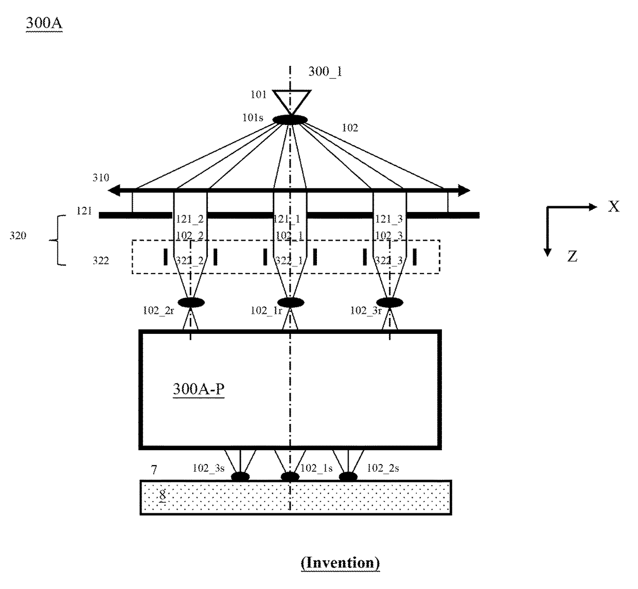
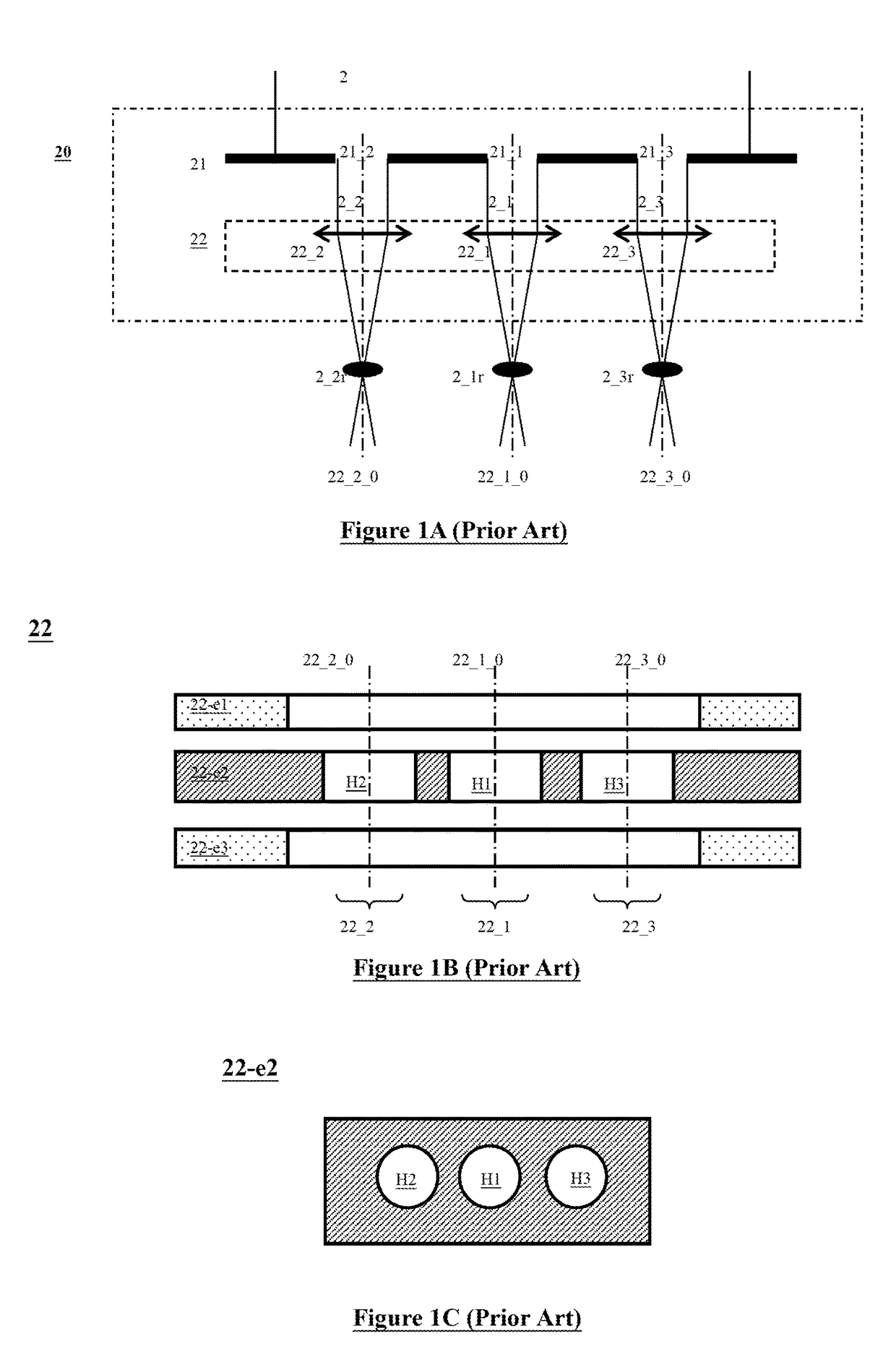
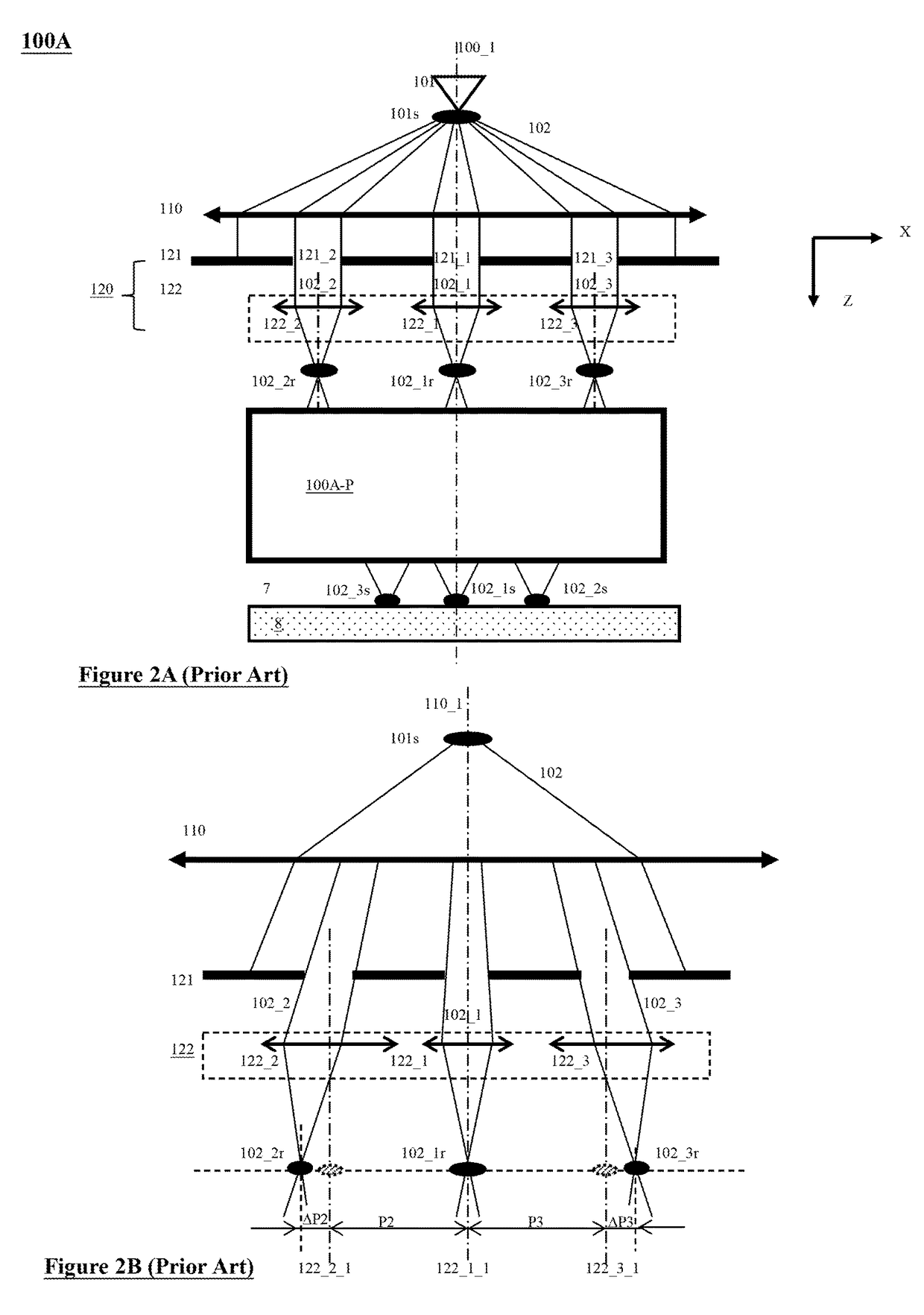
[0052]Various example embodiments of the present invention will now be described more fully with reference to the accompanying drawings in which some example embodiments of the invention are shown. Without limiting the scope of the protection of the present invention, all the description and drawings of the embodiments will exemplarily be referred to an electron beam. However, the embodiments are not be used to limit the present invention to specific charged particles.

[0053]In the drawings, relative dimensions of each component and among every component may be exaggerated for clarity. Within the following description of the drawings the same or like reference numbers refer to the same or like components or entities, and only the differences with respect to the individual embodiments are described.

[0054]Accordingly, while example embodiments of the invention are capable of various modifications and alternative forms, embodiments thereof are shown by way of example in the drawings and...


PUM


Abstract

A multi-beam apparatus for observing a sample with high resolution and high throughput and in flexibly varying observing conditions is proposed. The apparatus uses a movable collimating lens to flexibly vary the currents of the plural probe spots without influencing the intervals thereof, a new source-conversion unit to form the plural images of the single electron source and compensate off-axis aberrations of the plural probe spots with respect to observing conditions, and a pre-beamlet-forming means to reduce the strong Coulomb effect due to the primary-electron beam.

Description

CLAIM OF PRIORITY[0001]This application claims the benefit of priority of U.S. provisional application No. 62 / 194,925 entitled to Li et al. filed Jul. 21, 2015 and entitled “Apparatus of Plural Charged-Particle Beams”, the entire disclosures of which are incorporated herein by reference.BACKGROUND OF THE INVENTION[0002]1. Field of the Invention[0003]The present invention relates to a charged-particle apparatus with a plurality of charged-particle beams. More particularly, it relates to an apparatus which employs plural charged-particle beams to simultaneously acquire images of plural scanned regions of an observed area on a sample surface. Hence, the apparatus can be used to inspect and / or review defects on wafers / masks with high resolution and high throughput in semiconductor manufacturing industry.[0004]2. Description of the Prior Art[0005]For manufacturing semiconductor IC chips, pattern defects and / or uninvited particles (residuals) inevitably appear on a wafer and / or a mask dur...

Claims


Application Information

Patent Timeline
Patent Type & Authority Patents(United States)
IPC IPC(8): H01J37/28H01J37/10H01J37/244H01J37/20
CPCH01J37/28H01J37/10H01J2237/2817H01J37/20H01J37/244H01J2237/0453H01J2237/0492H01J2237/04924H01J2237/04926H01J2237/04928H01J2237/1205H01J2237/1501H01J2237/1502H01J2237/2446H01J2237/2448H01J2237/2806
Inventor LI, SHUAIREN, WEIMINGLIU, XUEDONGDOU, JUYINGHU, XUERANGCHEN, ZHONGWEI
Owner ASML NETHERLANDS BV
Why Eureka
Try Eureka