
Treatment of indications using electrical stimulation

a technology of electrical stimulation and indications, applied in the field of medical devices, can solve the problems of difficult or insufficient stimulation of tissues deep within the body, many non-targeted tissues may be co-activated with the targeted tissues, unwanted sensations and/or unwanted movements, etc., to reduce joint pain and/or arthritis pain, promote wound healing, and reduce or prevent muscle atrophy

Active Publication Date: 2018-03-27
BIONESS
View PDF141 Cites 0 Cited by
  • Summary
  • Abstract
  • Description
  • Claims
  • Application Information

AI Technical Summary

Benefits of technology

This approach enables targeted and efficient stimulation or blockade of neural impulses, improving treatment outcomes for various conditions like urinary incontinence, pain management, and muscle atrophy without the need for frequent device replacements or percutaneous wire maintenance.

Problems solved by technology

In other pathological states, action potentials are transmitted which do not serve a useful purpose; hence, blocking of unnecessary neural impulses is required to restore normal functioning.
However, all neural prostheses intended for long-term use require the implantation of a stimulator that contains electronic components and often a battery.
A disadvantage of stimulation through electrodes attached to the body surface is that many non-targeted tissues may be co-activated along with the targeted tissues.
This lack of selectivity often causes unwanted sensations and / or unwanted movements.
Furthermore, tissues that lie deep within the body can be difficult or impossible to stimulate adequately, because most of the electrical current flowing between the electrodes flows through tissues closer to the electrodes than the targeted tissues.
Implanted stimulators are expensive and often require a controller and / or power source external to the body.
This has generally limited the use of percutaneous electrodes to short-term applications.

Method used


Image

  • Treatment of indications using electrical stimulation
  • Treatment of indications using electrical stimulation
  • Treatment of indications using electrical stimulation

Examples


Embodiment Construction

[0028]Systems and methods are described herein that include the use of passive electrical conductors that can route electrical current to electrically stimulate a target body tissue. Such devices and methods can be used to either activate or block neural impulses, depending upon the frequency and the disorder to be treated.

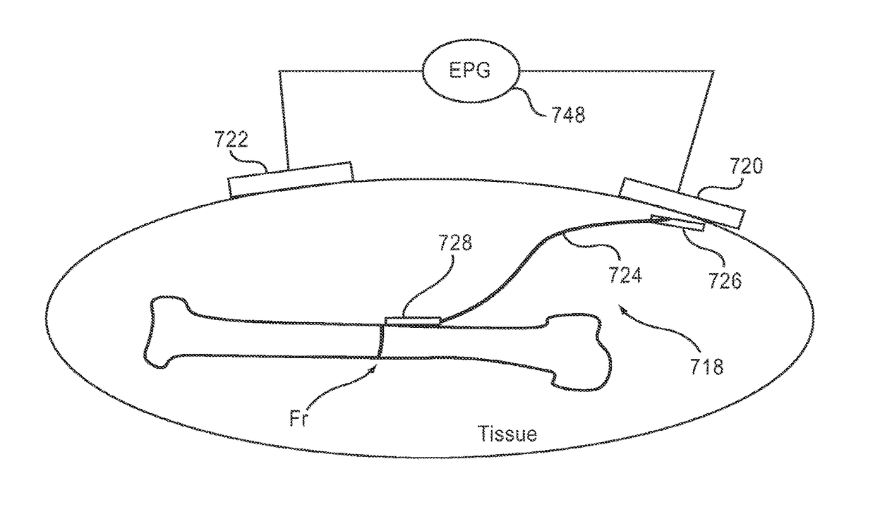
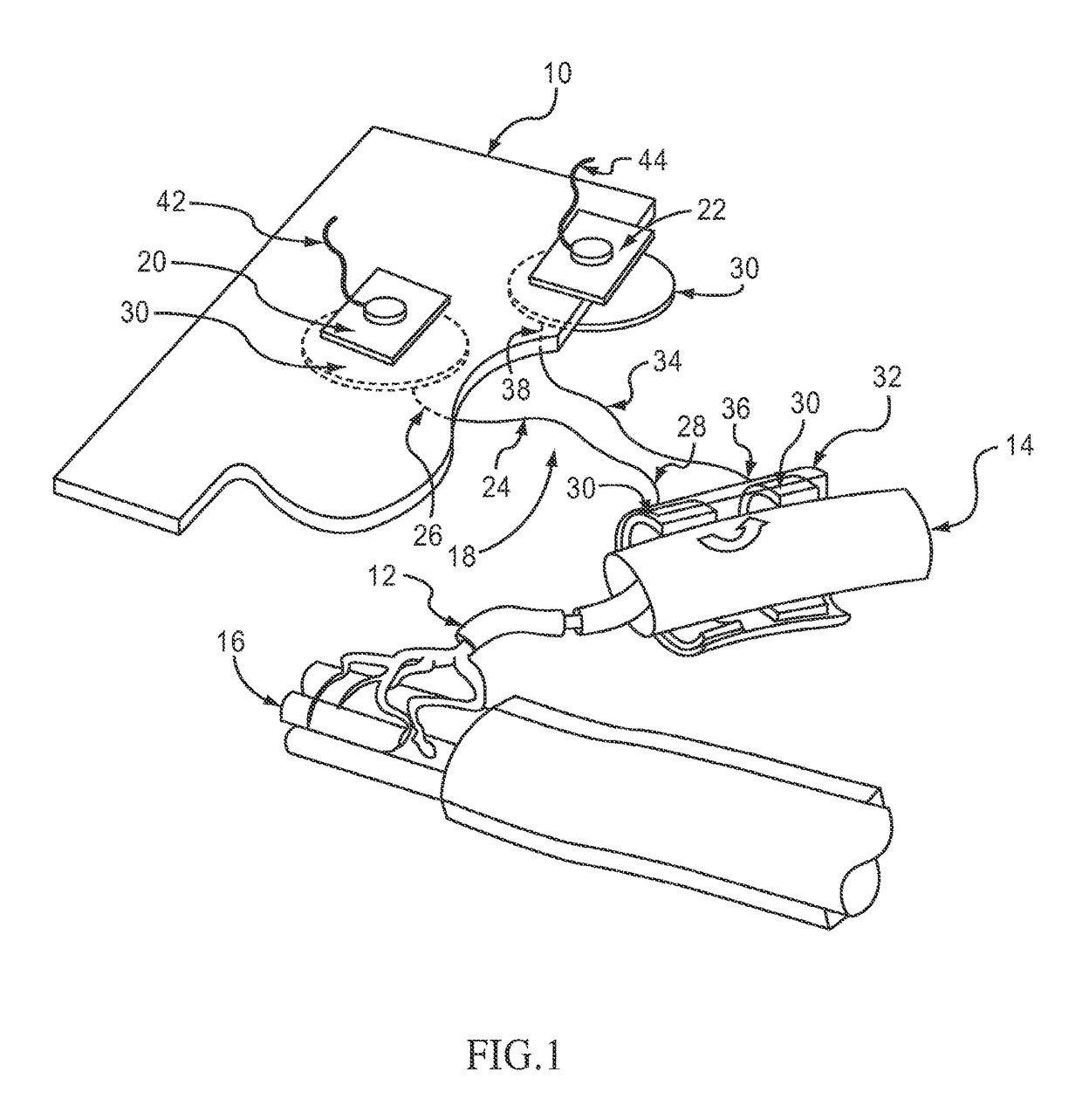
[0029]A system as described herein can include, for example, an implant, a stimulator, such as an electric pulse generator, external electrodes, and a power source. An implant is provided for electrically stimulating a target body tissue in a subject to either activate or block neural impulses. Once implanted, the implant can provide a conductive pathway for at least a portion of the electrical current flowing between surface cathodic and anodic electrodes positioned in spaced relationship on a subject's skin, and transmits that portion of electrical current to the target body tissue to either activate or block neural impulses. Systems and methods incorporating su...


PUM


Abstract

In one embodiment, a method includes implanting an implant entirely under the subject's skin. The implant includes a passive electrical conductor of sufficient length to extend from subcutaneous tissue located below one of a surface cathodic electrode and a surface anodic electrode to the tibial nerve. The surface electrodes are positioned in spaced relationship on the subject's skin, with one of the electrodes positioned over the pick-up end of the electrical conductor such that the portion of the current is transmitted through the conductor to the tibial nerve, and such that the current flows through the tibial nerve and returns to the other of the surface cathodic electrode and the surface anodic electrode. An electrical current is applied between the surface cathodic electrode and the surface anodic electrode to cause the portion of the electrical current to flow through the implant to stimulate the tibial nerve.

Description

CROSS-REFERENCE TO RELATED APPLICATIONS[0001]The application is a 35 U.S.C. § 371 national stage application of International Application No. PCT / US09 / 48419, filed Jun. 24, 2009, entitled “Treatment of Indications Using Electrical Stimulation,” which is a continuation-in-part and claims priority to and the benefit of U.S. Non-provisional application Ser. No. 12 / 147,937, filed Jun. 27, 2008, entitled “Treatment of Indications Using Electrical Stimulation,” the disclosure of which is incorporated herein by reference in its entirety.BACKGROUND[0002]The invention relates generally to medical devices and more particularly to devices and methods for use in electrical stimulation treatment.[0003]Nerve cells consist of an axon for transmitting action potentials or neural impulses, and dendrites for receiving such impulses. Normally, nerves transmit action potentials from the impulse-sending axon of one nerve cell to the impulse-receiving dendrites of an adjacent nerve cell. At synapses, the...

Claims


Application Information

Patent Timeline
Patent Type & Authority Patents(United States)
IPC IPC(8): A61N1/36A61N1/375
CPCA61N1/36007A61N1/375
Inventor GLUKHOVSKY, ARKADYLINDON, MARK L.ZILBERMAN, YITZHAK
Owner BIONESS
Learn More