Battery routing electric wire and wire harness

a wire harness and battery technology, applied in the direction of batteries, cables, insulated conductors, etc., can solve the problems of reducing the possibility of device breaking, reducing and preventing the increase of the number of processing steps

Active Publication Date: 2018-03-27
YAZAKI CORP
View PDF16 Cites 1 Cited by
  • Summary
  • Abstract
  • Description
  • Claims
  • Application Information

AI Technical Summary

Benefits of technology

[0009]The invention is made in order to solve the conventional problem described above and an object of the invention is to provide a battery routing electric wire and a wire harness in which an increase in processing steps can be prevented without limiting an orientation of terminals, while preventing breakage of a device due to an electrolytic solution.
[0011]According to the battery routing electric wire of the aspect of the invention, since the conduction portion is formed of the single wire, the electrolytic solution is difficultly to be sucked up due to the capillary phenomenon compared to a case of a twisted wire. In addition, since the cover portion is made of the polyvinyl chloride, the alkaline electrolytic solution is changed into water by a chemical reaction and sucking up of the electrolytic solution due to the capillary phenomenon is suppressed. Therefore, a possibility of the liquid extending to the device can be reduced. Furthermore, there is no need to cause the orientation of terminals attached to the electric wire to be a predetermined direction or to perform a water repelling process such as soldering in the terminals of the electric wire. Therefore, it is possible to prevent an increase in the number of processing steps without limiting the orientation of the terminals while preventing breakage of the device due to an electrolytic solution.
[0013]According to the battery routing electric wire, when 72 hours have elapsed in a state in which one end surface of the electric wire is immersed in the alkaline electrolytic solution by 10 mm, and the entire electric wire is disposed to be substantially semicircular, the traveling length of the liquid between the conduction portion and the cover portion is equal to or less than 200 mm. Therefore, if the battery and the device are connected by an electric wire having a length exceeding 200 mm, it is possible to reduce a possibility of the liquid reaching the device even when the electrolytic solution leaks.
[0015]According to the battery routing electric wire, the polymerization degree of the polyvinyl chloride is equal to or greater than 1000. Therefore, a possibility of the liquid extending to the device can be reduced. A possibility of breakage of the device can be further reduced.
[0017]According to the wire harness, it is possible to provide the wire harness in which a possibility of the device breaking is reduced and it is possible to prevent an increase in the number of processing steps.
[0018]According to aspects of the invention, it is possible to provide the battery routing electric wire and the wire harness using the battery routing electric wire in which a possibility of the device breaking is reduced and it is possible to prevent an increase in the number of processing steps.

Problems solved by technology

Scarcely any of the generated gas is discharged to the outside during normal charging and discharging.
Gas is abnormally generated during forced discharging in an over-discharge state, during continued over-charging, and during discharging a large current and during short-circuiting causing a rapid temperature rise, thereby not being absorbed in the inside of the battery.
However, in a case where the safety valve described above is operated, the electrolytic solution in the inside thereof may leak at the same time as the discharge of gas.
In addition, the electrolytic solution may leak due to various reasons such as creep deformation due to a battery temperature rise other than during the operation of the safety valve.
However, in the countermeasure described in JP-A-2010-257686, the orientation of the terminals is limited or an increase in the number of processing steps due to the sealing material is caused.

Method used


Image

  • Battery routing electric wire and wire harness
  • Battery routing electric wire and wire harness
  • Battery routing electric wire and wire harness

Examples


Embodiment Construction

[0027]Hereinafter, a preferable embodiment of the invention will be described with reference to the drawings, but the invention is not limited to the following description and can be appropriately changed within a range without departing from the spirit of the invention.

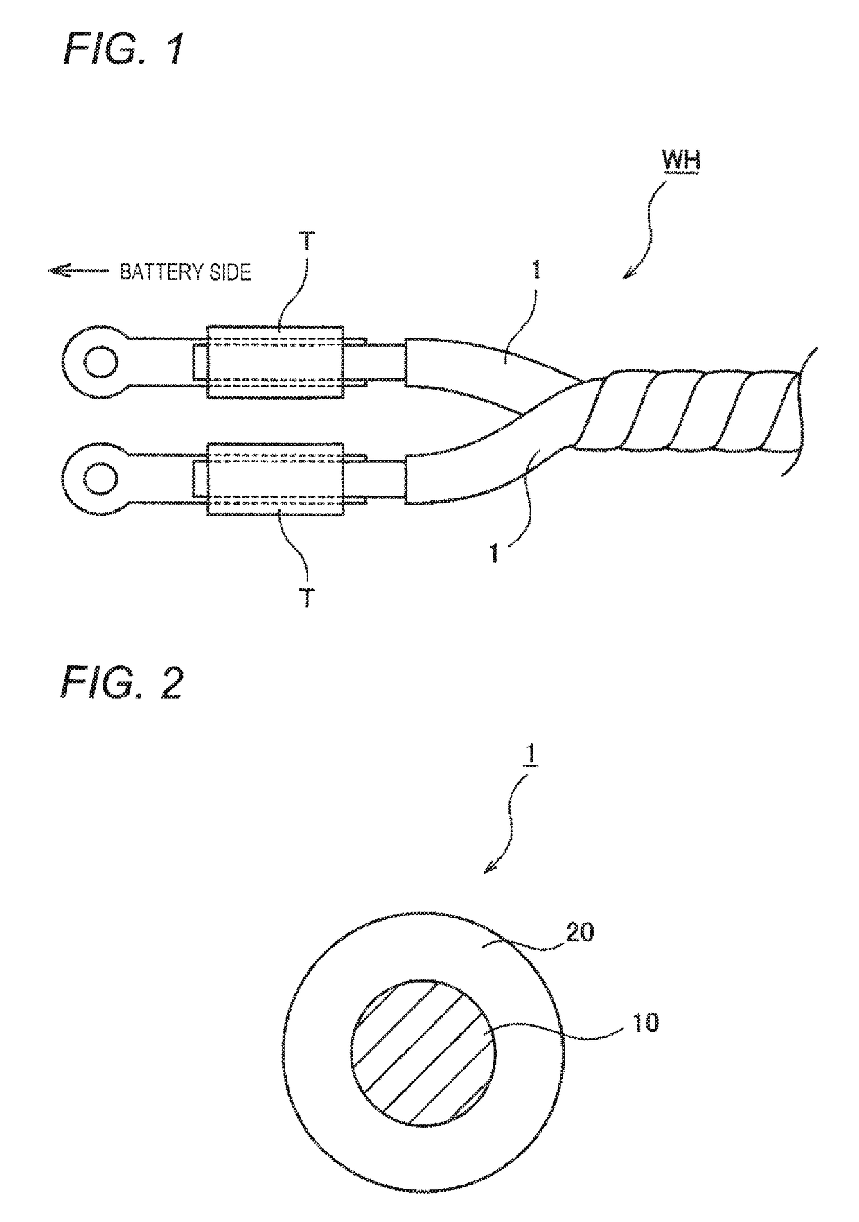
[0028]FIG. 1 is a view of a wire harness including a battery routing electric wire according to an embodiment. As illustrated in FIG. 1, a wire harness WH is configured of at least one battery routing electric wire 1 and another component (at least one of an electric wire of the same type or different types, a terminal, a connector, a tape, and a corrugated tube), and, in the embodiment, is configured to include a plurality (two) of battery routing electric wires 1. The plurality of battery routing electric wires 1 are collectively tape-wounded.

[0029]Such a wire harness WH includes, for example, LA-terminals T at end portions of at least one side of the battery routing electric wires 1, the LA-terminals T are connect...


PUM

PropertyMeasurementUnit
traveling lengthaaaaaaaaaa
lengthaaaaaaaaaa

Abstract

A battery routing electric wire is routed between a battery having an alkaline electrolytic solution and a device. The battery routing electric wire includes: a conduction portion formed of a single wire; and a cover portion that covers the conduction portion and is made of polyvinyl chloride.

Description

CROSS-REFERENCE TO RELATED APPLICATION(S)[0001]This application is based on and claims priority from Japanese Patent Application (Application No. 2015-187728) filed on Sep. 25, 2016, the entire contents of which are incorporated herein by reference.BACKGROUND[0002]1. Field of the Invention[0003]The present invention relates to a battery routing electric wire and a wire harness.[0004]2. Description of Related Art[0005]In the related art, it is known that a battery that is formed by connecting a plurality of unit cells in series is mounted on a HEV vehicle and the like. As such a battery, for example, it is known that a nickel hydride battery is used. An electrolytic solution is sealed in the nickel hydride battery and some gas is generated in an inside of the nickel hydride battery during charging and discharging. Scarcely any of the generated gas is discharged to the outside during normal charging and discharging. Gas is abnormally generated during forced discharging in an over-disc...

Claims


Application Information

Patent Timeline
Patent Type & Authority Patents(United States)
IPC IPC(8): H01M2/34H01B3/44H01B7/00H01M50/588H01M50/591
CPCH01M2/34H01B3/445H01B7/0045H01M2220/20H01M2200/00H01B7/28Y02E60/10H01M50/591H01M50/588
Inventor TOSAYA, YUKIKONDO, HIROKIYASUDA, NAMIKO
Owner YAZAKI CORP
Why Eureka
Try Eureka