Method and engine brake system to control an engine brake of a vehicle

a technology of engine brakes and brake systems, which is applied in the direction of machines/engines, electrical control, valve arrangements, etc., can solve the problems of inability to control the brake torque, inability to continuously control the brake torque of the engine, and the inability to regulate the engine brake torque indefinitely or in small discrete steps, so as to avoid unnecessary switching between the two modes of regulation

Active Publication Date: 2018-04-10
VOLVO LASTVAGNAR AB
View PDF12 Cites 3 Cited by
  • Summary
  • Abstract
  • Description
  • Claims
  • Application Information

AI Technical Summary

Benefits of technology

[0003]The EPG controls the pressure downstream of the cylinders, wherein a closing of the EPG usually leads to a higher exhaust manifold pressure, thereby a higher engine brake torque. The EPG is usually controlled with a closed-loop control with the exhaust pressure as feedback signal.
[0030]It is further preferred that said engine torque threshold value comprises a first and a second engine torque threshold value, wherein said first engine torque threshold value is lower than said second engine torque threshold value, and said engine speed threshold value comprises a first and a second engine speed threshold value, wherein said first engine speed threshold value is lower than said second engine speed threshold value, wherein said first threshold values are used when the reference value increases and the second threshold value are used when the reference value decreases. By using a hysteresis function as described above, unnecessary switching between the two modes of regulation are avoided in the bounder areas.

Problems solved by technology

For some engines, especially turbo compound engines, and at some engine speeds, it is not possible to control the brake torque contribution from the compression brake between a zero brake torque contribution from the compression brake when it is deactivated and the maximum brake torque contribution from the compression brake that can be achieved with the compression brake activated.
Due to the fact that the compression brake is activated by an ON / Off valve, continuous control of engine brake torque is not possible between the maximum torque that can be reached with only the EPG and the torque that is reached with the compression brake only.
Hence, during some conditions, the engine brake torque regulation cannot be regulated indefinitely or in small discrete steps, instead just in an on / off mode, due to the on / off regulation of the compression brake.

Method used


Image

  • Method and engine brake system to control an engine brake of a vehicle
  • Method and engine brake system to control an engine brake of a vehicle
  • Method and engine brake system to control an engine brake of a vehicle

Examples


Embodiment Construction

[0037]In the following only one embodiment of the invention is shown and described, simply by way of illustration of one node of carrying out the invention. The invention is not limited to the specific diagrams presented, but includes all variations within the scope of the present claims.

[0038]Reference signs mentioned in the claims should not be seen as limiting the extent of the matter protected by the claims, and their sole function is to make claims easier to understand.

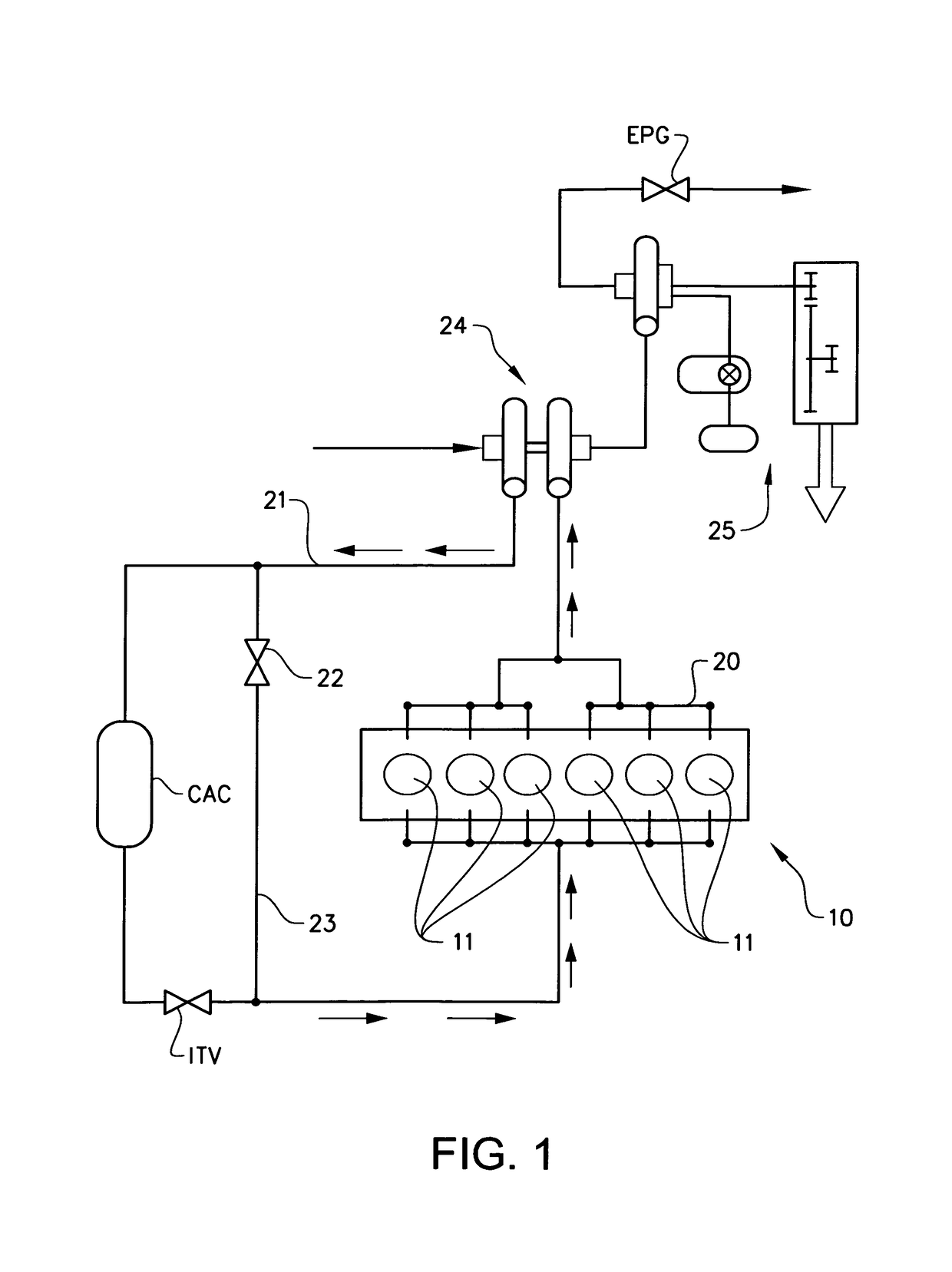
[0039]FIG. 1 shows a schematic view of an engine (10) and its air intake and exhaust gas flows, in FIG. 1 is only flows relevant for the invention disclosed. The engine (10) comprises six cylinders (11), the number of cylinders is however not important for the invention. The air intake flow is regulated by an intake air throttle valve (ITV) arranged in the air intake channel (21). A charge air cooler (CAC) is arranged upstream in the intake air flow, the CAC is able to cool the intake air flow. A CAC bypass-valve...


PUM


Abstract

A method and system to control an engine brake of a vehicle is provided. The vehicle is provided with a combustion engine having cylinders, an exhaust pressure governor (EPG) regulating the air flow out of the cylinders, an intake air throttle valve (ITV) regulating the air flow into the cylinders, pressure sensing means for sensing a pressure downstream of the cylinders, wherein an engine braking torque can be regulated in two different engine braking modes (a, b), ⋅a first engine braking mode (a), in which the air flow through the EPG is regulated by a closed loop control using the pressure downstream of the cylinders and the ITV is regulated in a feed forward control dependent of the engine speed and a demanded brake torque; ⋅a second engine braking mode (b), in which the EPG is regulated in a feed forward control dependent of the engine speed and the demanded brake torque, and the ITV regulates the braking torque by a closed loop control using the pressure downstream of the cylinders.

Description

BACKGROUND AND SUMMARY[0001]The present invention relates to the field of engine brakes of a vehicle. Especially for a vehicle provided with a combustion engine having cylinders with cylinder valves an exhaust pressure governor (EPG) regulating the air flow out of the cylinders and an intake air throttle valve (ITV) regulating the air flow into the cylinders.[0002]Engine brakes which comprise a compression brake and an exhaust pressure governor (EPG) are known. The compression brake closes the cylinders valves, such that the air therein is compressed, whereby a brake torque is created. Normally, the compression brake is controlled by an on / off valve.[0003]The EPG controls the pressure downstream of the cylinders, wherein a closing of the EPG usually leads to a higher exhaust manifold pressure, thereby a higher engine brake torque. The EPG is usually controlled with a closed-loop control with the exhaust pressure as feedback signal.[0004]The total engine brake torque is a combination...

Claims


Application Information

Patent Timeline
Patent Type & Authority Patents(United States)
IPC IPC(8): F02D9/02F02D9/06F02D41/14F01L13/06
CPCF02D9/06F01L13/06F02D41/1448F02D9/02F02D2009/0242F02D2009/023
Inventor HELLEMANN, FABIAN
Owner VOLVO LASTVAGNAR AB
Why Eureka
Try Eureka