
Power converter and method for manufacturing power converter

a technology of power converter and manufacturing method, which is applied in the direction of power conversion system, semiconductor/solid-state device details, semiconductor devices, etc., can solve the problem of resin thermal conductivity being lower than that of metal

Active Publication Date: 2018-04-10
TOYOTA JIDOSHA KK
View PDF21 Cites 3 Cited by
  • Summary
  • Abstract
  • Description
  • Claims
  • Application Information

AI Technical Summary

Benefits of technology

This patent describes a power converter with a cooler and power card that are laminated together, making it highly strong. The cooler is made of a resin body that is easily formed into complex shapes but has lower thermal conductivity than metal. To ensure efficient cooling, a metal plate is used as a heat transfer member inside the cooler, which is in direct contact with the power card. The metal plate and the opening in the resin body are sealed using pressure, making it simpler to seal the opening. This results in a highly strong and efficient power converter with good cooling efficiency.

Problems solved by technology

However, thermal conductivity of resin is lower than that of metal such as aluminum.

Method used


Image

  • Power converter and method for manufacturing power converter
  • Power converter and method for manufacturing power converter
  • Power converter and method for manufacturing power converter

Examples


Embodiment Construction

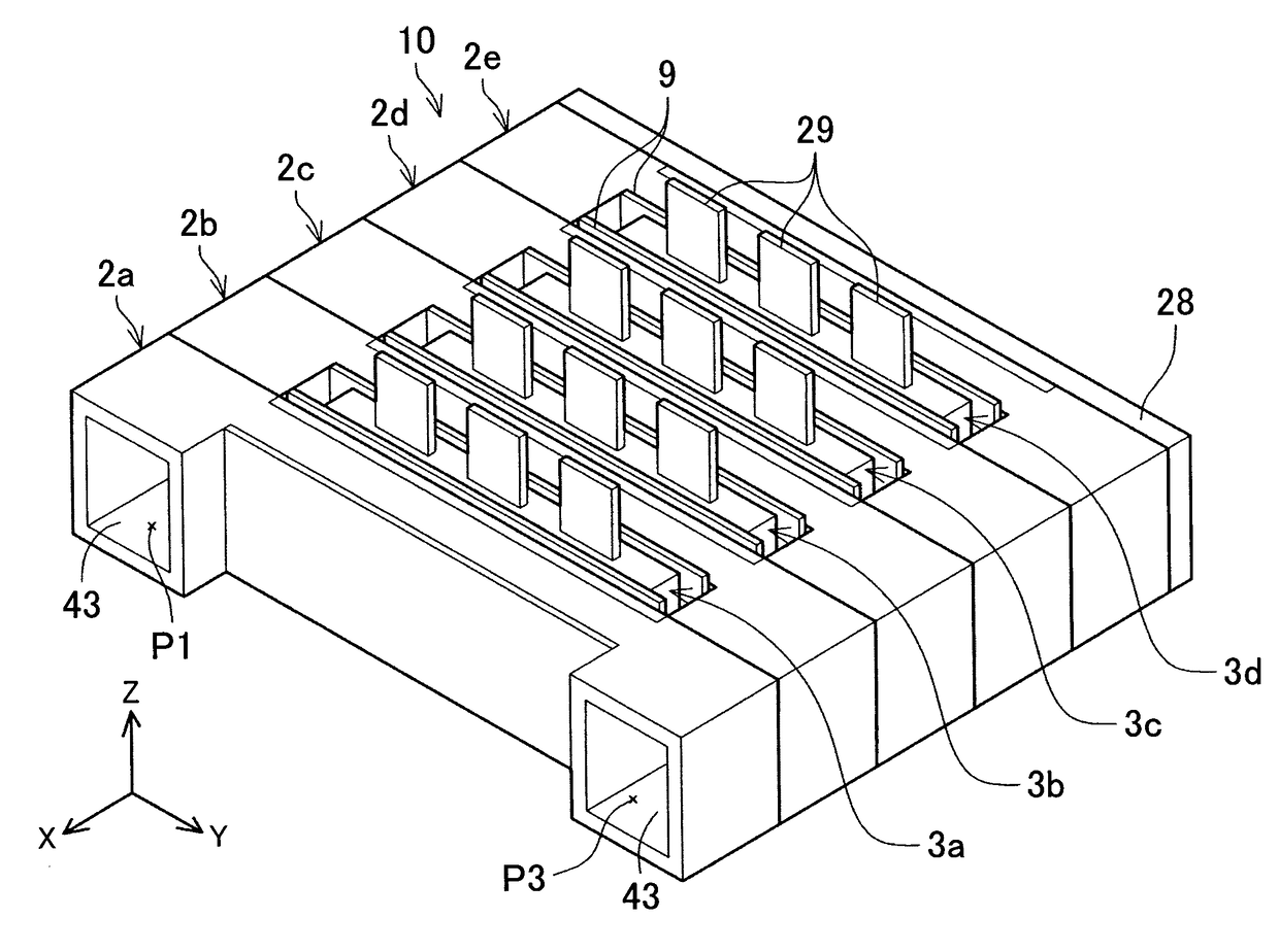
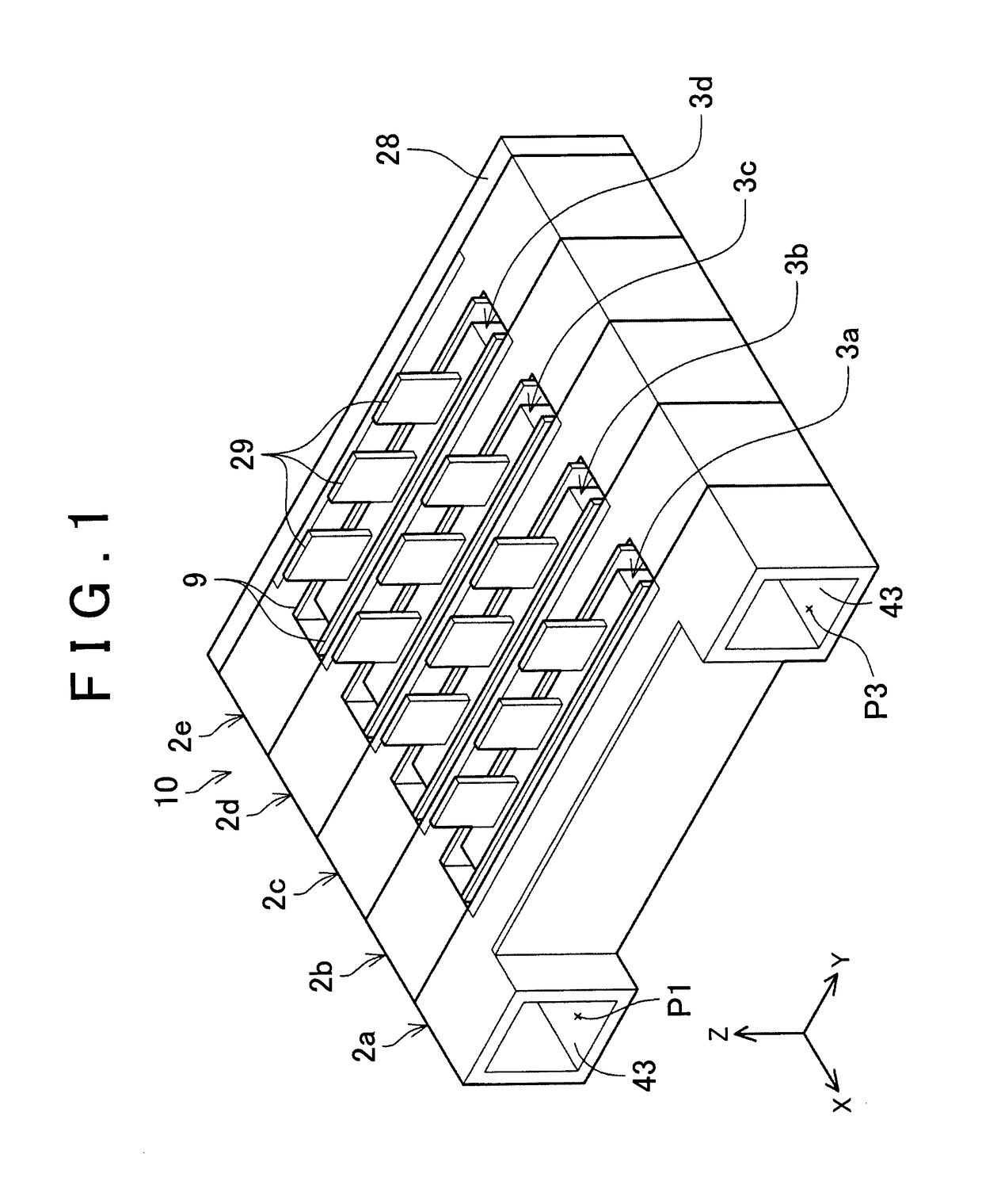
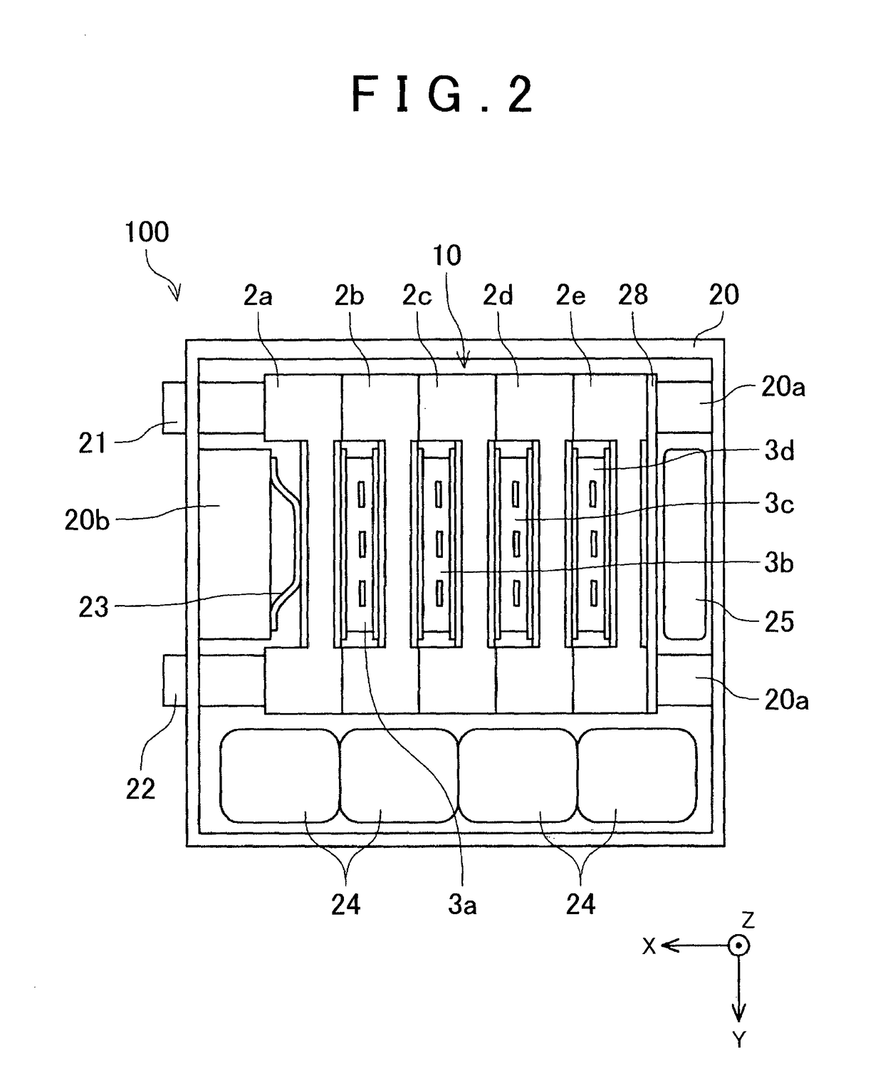
[0029]A power converter according an example is explained with reference to the drawings. First of all, an outline of a lamination unit is provided. FIG. 1 shows a perspective view of a lamination unit 10. The lamination unit 10 is a main component of a power converter mounted on an electric vehicle. The power converter boosts direct-current power of a battery, further converts the direct-current power into an alternating current, and supplies the power to a motor for running. The power converter includes a voltage converter circuit that increases voltage, and an inverter circuit. The voltage converter circuit is a step-up / step-down converter and includes two semiconductor elements (IGBTs). The inverter circuit includes six semiconductor elements. The power converter includes eight semiconductor elements in total. Each of the semiconductor elements generates a large amount of heat because the semiconductor element conducts and brakes large current. The number of the semiconductor el...


PUM


Abstract

A power converter includes a plurality of power cards, a plurality of coolers and a pressure member. Each of the power cards houses a semiconductor element. The plurality of coolers is laminated with the power cards. The cooler includes a body, a gasket and a metal plate. The body is made of resin, and has an opening that is provided in a side surface of the cooler that faces the adjacent power card. A surface on one side of the metal plate is configured to close the opening through the gasket, and the other surface faces the power card. The pressure member is configured to apply a pressure in a laminating direction on a lamination unit. The opening is sealed by the metal plate by pressure applied by the pressure member on the lamination unit.

Description

BACKGROUND OF THE INVENTION[0001]1. Field of the Invention[0002]The invention relates to a power converter and a method for manufacturing the power converter. The invention especially relates to a power converter, in which a plurality of power cards that respectively house semiconductor elements, and a plurality of coolers are laminated, and to a method for manufacturing the power converter.[0003]2. Description of Related Art[0004]A power converter generates a large amount of heat. A switching element, or a semiconductor element for power conversion, which is called a power element, generates a particularly large amount of heat. For example, a power converter that supplies power to an electric vehicle driving motor is provided with a large number of switching elements, and thus generates an especially large amount of heat.[0005]Japanese Patent Application Publication No. 2012-238681 (JP 2012-238681 A), Japanese Patent Application Publication No. 2006-165534 (JP 2006-165534 A), and J...

Claims


Application Information

Patent Timeline
Patent Type & Authority Patents(United States)
IPC IPC(8): H01L23/34H01L25/00H01L21/48H01L25/11H02M7/00H01L23/473H01L23/40H02M7/537
CPCH01L23/4012H01L21/4882H01L23/40H01L23/473H01L25/117H01L25/50H02M7/003H02M7/537H01L2924/0002H01L2924/00
Inventor YOSHIDA, TADAFUMI
Owner TOYOTA JIDOSHA KK
Learn More