Wave fins

a technology of wave fins and fins, which is applied in the direction of tubular elements, lighting and heating apparatus, laminated elements, etc., can solve the problems of loss of kinetic energy during fluid flow, the turbulent kinetic energy of fluid that passes through individual fluid passages is not substantially enhanced, and the fluid heat exchange efficiency is improved. , to achieve the effect of increasing the turbulent kinetic energy and improving the heat exchange efficiency of fluid

Inactive Publication Date: 2018-04-17
KORENS
View PDF15 Cites 3 Cited by
  • Summary
  • Abstract
  • Description
  • Claims
  • Application Information

AI Technical Summary

Benefits of technology

[0017]According to the present invention, the bent portions formed on the sidewalls accelerate the tendency of fluid to become turbulent, thereby significantly increasing turbulent kinetic energy. This consequently improves the heat exchange efficiency of the fluid, which is advantageous.

Problems solved by technology

However, since the heat exchanger housing has a relatively small interior volume, there are several limitations against the ability of conventional wave fins to enhance the turbulence of fluid.
In particular, since the surface of the conventional wave fins is smooth, the turbulent kinetic energy of fluid that passes through individual fluid passages is not substantially enhanced.
In addition, a loss in kinetic energy occurs while fluid is flowing.
Accordingly, the heat exchange efficiency of fluid is not substantially high, which is problematic.

Method used


Image

  • Wave fins
  • Wave fins
  • Wave fins

Examples


Embodiment Construction

[0028]Hereinafter an exemplary embodiment of the present invention will be described in detail in conjunction with the accompanying drawings.

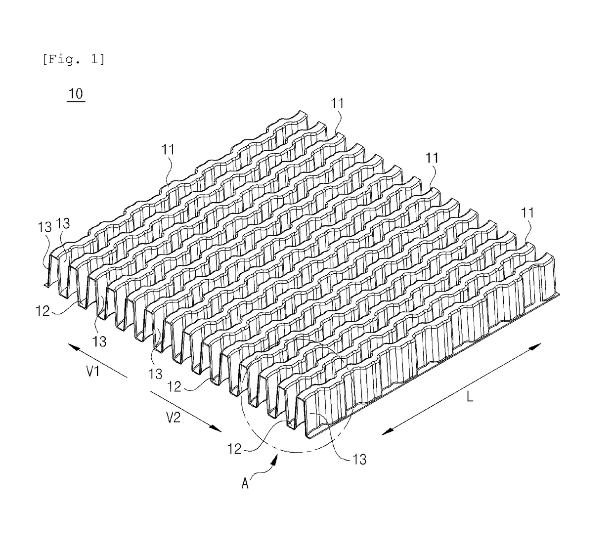
[0029]FIGS. 1 to 6 are views showing wave fins according to an embodiment of the present invention.

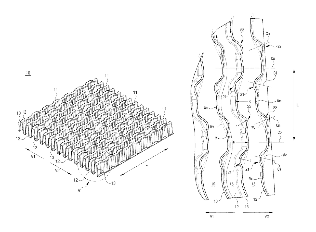
[0030]As shown in the figures, the wave fins 10 according to the present invention include a plurality of hills 11 and a plurality of valleys 12 which continuously extend at preset distances along transverse directions V1 and V2 of the wave fins 10. The plurality of hills 11 is connected to the plurality of valleys 12 via a plurality of sidewalls 13 in the transverse direction.

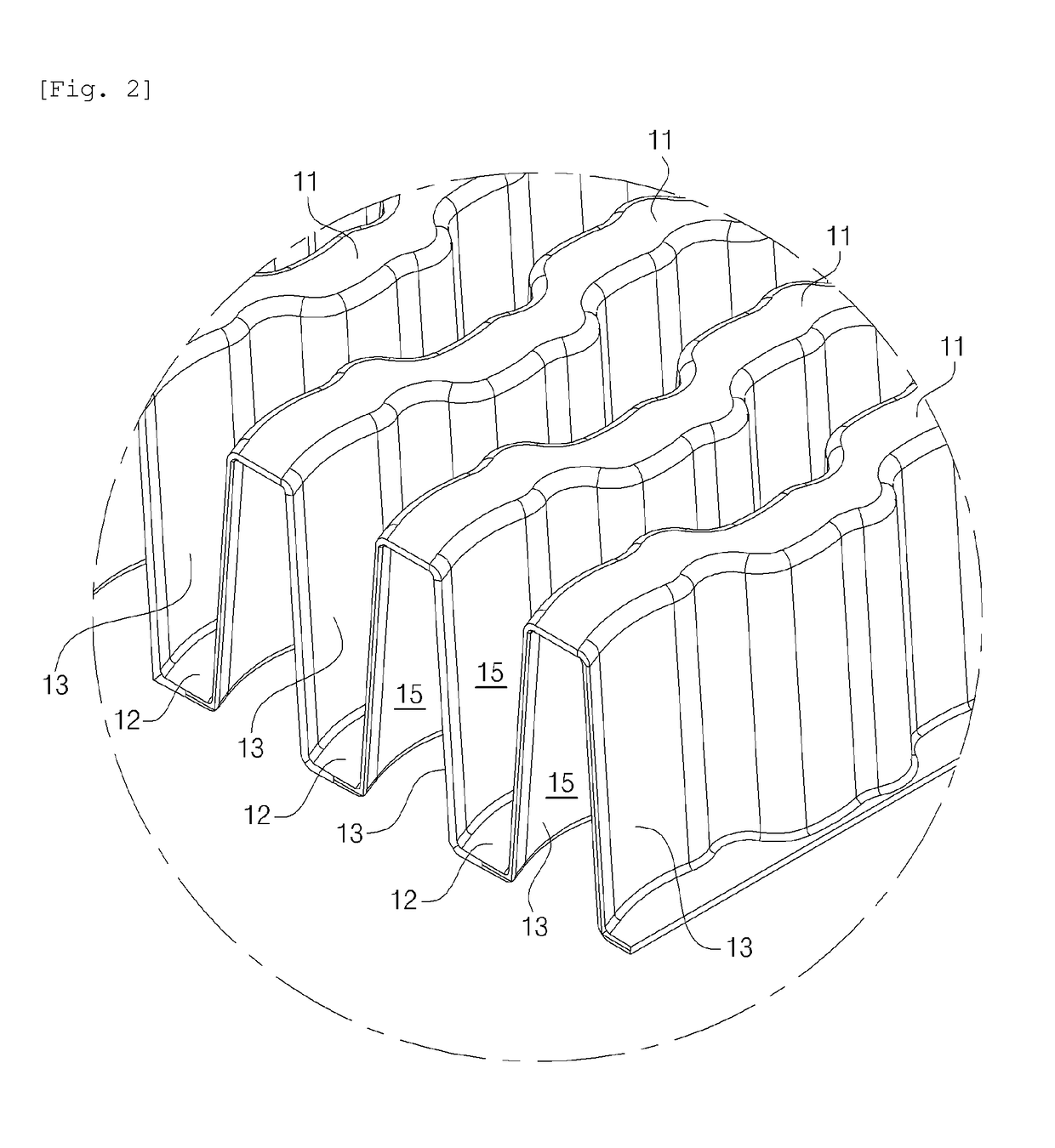
[0031]The wave fins 10 have a plurality of fluid passages 15 which are partitioned by the plurality of sidewalls 13. The upper ends and lower ends of the fluid passages 15 are alternately closed by the plurality of hills 11 and the plurality of valleys 12.

[0032]As shown in FIGS. 4 and 5, each of the fluid passages 15 may form a trapezoidal cross-sectional structure as the si...


PUM


Abstract

Wave fins which are disposed inside a heat exchanger housing of a heat exchanger in order to cause a turbulent flow of fluid through direct contact with the fluid. The wave fins include a plurality of hills, a plurality of valleys and a plurality of sidewalls. The hills and valleys are connected to each other via the plurality of sidewalls. The sidewalls partition fluid passages between the hills and the valleys through which fluid passes. The hills, the valleys and the sidewalls form main waveforms that extend in a longitudinal direction so as to be waved in a first radius of curvature. One or more bent portions are formed on intermediate portions of the main waveforms, the bent portions being connected to remaining portions of the main waveforms so as to be bent at a second radius of curvature.

Description

TECHNICAL FIELD[0001]The present invention relates to wave fins which are disposed inside a heat exchanger housing of a heat exchanger in order to cause a turbulent flow of fluid through direct contact with the fluid, and more particularly, to wave fins which can promote the tendency of fluid to become turbulent and effectively improve the heat exchange efficiency of the fluid by significantly increasing the turbulent energy of the fluid.BACKGROUND ART[0002]A variety of heat exchangers, including an exhaust gas cooler for a vehicle such as an exhaust gas recirculation (EGR) cooler for recycling exhaust gas, a fuel cooler, an oil cooler, an intercooler, a superheater of a waste heat recovery system and a boiler, is used. Heat exchangers are configured to exchange heat between various types of fluid, such as gas-gas, liquid-gas and liquid-liquid. For instance, EGR can extract a portion of exhaust gas from an exhaust system of a diesel engine, circulate the extracted portion of exhaust...

Claims


Application Information

Patent Timeline
Patent Type & Authority Patents(United States)
IPC IPC(8): F28F3/02F28F1/12F28F13/06F28F13/12
CPCF28F3/025F28F13/12F28F13/06F28F1/126F28F1/10
Inventor CHO, YONG KUK
Owner KORENS
Why Eureka
Try Eureka