
Gearset with an air-guiding cover

a technology of air-guiding cover and gearset, which is applied in the direction of gearing elements, belts/chains/gears, gear lubrication/cooling, etc., can solve the problems of limiting the admissible mechanical power of the respective gearset, plurality of attachments, and very hot gearsets, so as to achieve efficient cooling of the gearset and effectively deflect the air flow. , the effect of cost-effectiv

Active Publication Date: 2018-04-24
FLENDER GMBH
View PDF26 Cites 11 Cited by
  • Summary
  • Abstract
  • Description
  • Claims
  • Application Information

AI Technical Summary

Benefits of technology

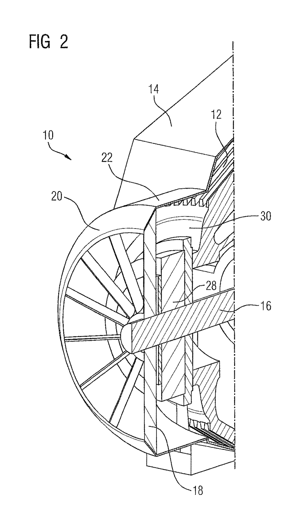
[0011]An advantage of the present invention resides in the fact that the conical section of the air-guiding cover is simultaneously effective in enclosing the radial fan and in deflecting an air flow generated by the radial fan in the direction of the gearset housing. Compared to axial fans, more cost-effective radial fans, which are independent of direction of rotation, can thus be used for realizing an efficient cooling of a gearset. There is no need for additional parts to effect air deflection. Since the conical section surrounds the radial fan directly, it is ensured that the air flow conveyed by the radial fan strikes the inside surface of the conical section of the air-guiding cover directly, without obstruction and turbulence as a result of, for example, components or construction elements located in the radial direction between the ends of the fan blades and the inside surface of the conical section. Thus, the conical section is thus able to effectively deflect the air flow. Since the conical section surrounds the radial fan without any dead space, it is ensured that the initially radially accelerated volume flow continues as an axial volume flow following the conical section without encountering flow losses as a result of turbulence or the like, as this would be expected in the case of a geometry that also causes a defection but does not surround the fan without any dead space. This enclosure of the radial fan without any dead space ensures that the air flow conveyed by the radial fan is optimally conducted onward and thus available in its entirety, or at least substantially in its entirety, for cooling of the gearset, i.e. cooling of the gearset by cooling the gearset housing.
[0012]According to another advantageous feature of the present invention, the conical section can have an opening angle which can basically be freely chosen depending on the application. Opening angles in the range of 40° to 50°, in particular 45°, are currently preferred. Greater opening angles cause increased pressure and a reduced volume flow. An appropriate opening angle can accordingly be chosen depending on the desired pressure / volume flow. This results in different air-guiding covers adapted to specific cooling requirements.
[0013]A further advantage of the present invention resides in the fact that the cylindrical section of the air-guiding cover adjoining the conical section (in the flow direction) is effective in channeling the air flow in the direction of the gearset housing. Advantageously, the cylindrical section defines a longitudinal axis which can run parallel to the drive shaft of the gearset. Advantageously, the longitudinal axis coincides with a longitudinal axis of the drive shaft. This channeling has two effects: firstly, the air flow is guided in the direction of the gearset housing. Secondly, the air flow is guided past one or more attachment(s) of the gearset, optionally located in the region of the cylindrical section.
[0014]In this way, ambient air drawn in by the radial fan can flow around and thereby cool attachments of the gearset, for example a non-return device, one or more planetary gear stage(s), a brake, a measuring element or a plurality of measuring elements fixed in the region of the cylindrical section. The length of the cylindrical section can be adapted to a respective number and / or dimension of the or each attachment as required. Following the cylindrical section of the air-guiding cover, the ambient air drawn in by the radial fan can strike the gearset housing (impingement cooling) and can cause intense cooling of the gearset housing, as a result of the impingement cooling, to thereby cool the gearset and, in the further course of the air flow through the gap remaining between air-guiding cover and gearset housing, to further cool the gearset.
[0015]According to another advantageous feature of the present invention, ambient air drawn in by the radial fan can be deflected by the conical section and flows through the cylindrical section to subsequently effectively cool the gearset housing by impingement cooling. The diameter of the cylindrical section is hereby dimensioned and the cylindrical section is positioned inside the air-guiding cover and in respect of the gearset housing such that an imaginary circular area resulting due to the cylindrical section and projected in the axial direction of the cylindrical section falls completely, or at least substantially, on a side surface (front surface) of the gearset housing. The side surface of the gearset housing against which air flows, will hereinafter be referred to as front surface of the gearset housing, as the drive shaft exits there. Since the cylindrical section of the air-guiding cover is oriented in respect to the front surface such that the surface normal of the front surface runs parallel, or at least substantially parallel, to the longitudinal axis of the cylindrical section, air which is drawn in by the radial fan can be deflected by the radial section of the air-guiding cover and channeled by the cylindrical section of the air-guiding cover to strike the front surface of the gearset housing perpendicularly or substantially perpendicularly and thereby realize an optimum cooling of the surface of the gearset housing.
[0016]According to another advantageous feature of the present invention, the radial fan can have a fan hub provided with a bevel or a radius, with the radial fan being fixed to the drive shaft by the fan hub. The conical section of the air-guiding cover enclosing the radial fan causes the above-described deflection of the radial air flow generated by the radial fan in the direction of the gearset housing. With a radial fan having a fan hub, which is provided with a bevel or a radius, a geometry of this kind assists a first deflection of the drawn-in air in the radial direction and avoids flow loss in the region of the fan hub.

Problems solved by technology

Gearsets become very hot due to the power loss that occurs during operation.
An oil temperature that is established in the gearset limits the admissible mechanical power of the respective gearset.
External oil cooling systems are often undesirable, so cooling has to take place by way of air (ambient air) surrounding the gearset.
In the event, the gearset includes cylindrical attachments, for example an attachment in the form of a non-return device, which are mounted on the drive shaft, there is a problem that cooling of the gearset by ambient air requires a bridging of an attachment of this kind, or a plurality of attachments.

Method used


Image

  • Gearset with an air-guiding cover
  • Gearset with an air-guiding cover
  • Gearset with an air-guiding cover

Examples


Embodiment Construction

[0023]Throughout all the figures, same or corresponding elements may generally be indicated by same reference numerals. These depicted embodiments are to be understood as illustrative of the invention and not as limiting in any way. It should also be understood that the figures are not necessarily to scale and that the embodiments may be illustrated by graphic symbols, phantom lines, diagrammatic representations and fragmentary views. In certain instances, details which are not necessary for an understanding of the present invention or which render other details difficult to perceive may have been omitted.

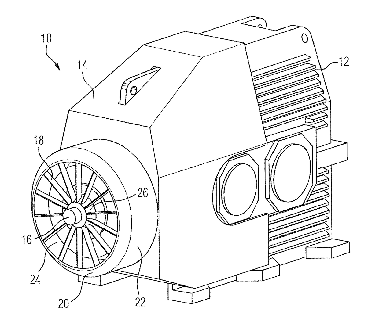
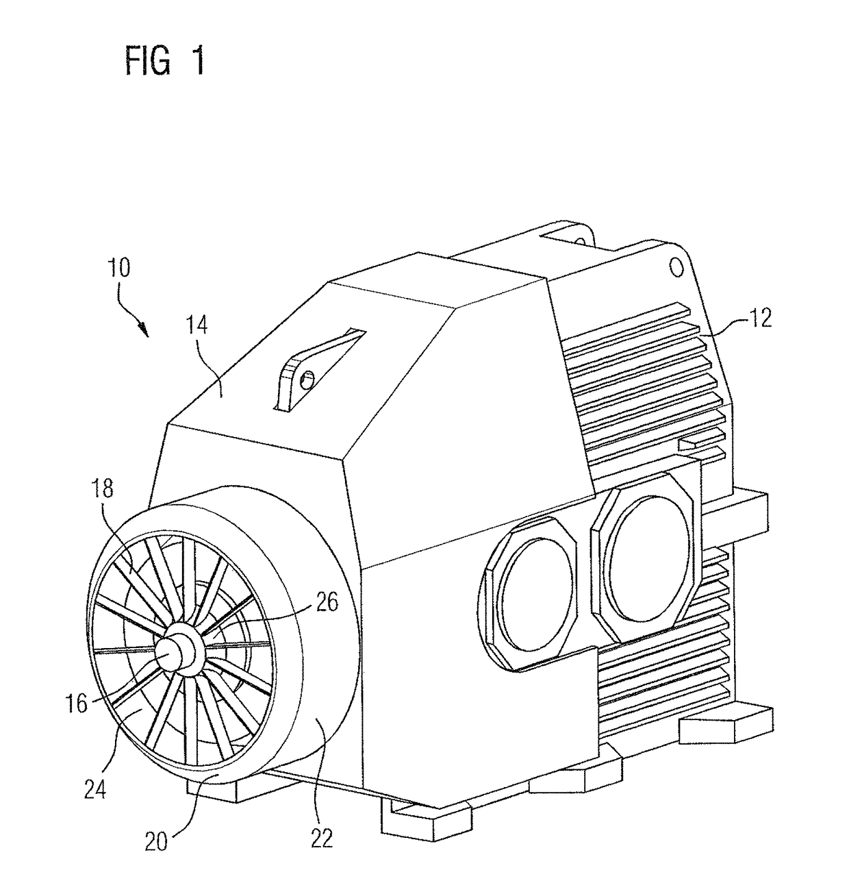
[0024]Turning now to the drawing, and in particular to FIG. 1, there is shown a top and side perspective illustration of a gearset having an air-guiding cover 10 in accordance with the present invention. The air-guiding cover 10 is shown in a state fixed to a housing (gearset housing 12) of the gearset. Part of the air-guiding cover 10 covers part of the gearset housing 12. This pa...


PUM


Abstract

A gearset includes a gearset housing, a drive shaft, and a radial fan fixed to the drive shaft. Disposed in surrounding relationship to the radial fan is an air-guiding cover which includes a gearset housing section to at least partially cover the gearset housing, a cylindrical section adjoining the gearset housing section and configured to receive an attachment for securement to the drive shaft, and a conical section adjoining the cylindrical section. The conical section of the air-guiding cover is disposed in surrounding relationship to the radial fan directly and without any dead space.

Description

CROSS-REFERENCES TO RELATED APPLICATIONS[0001]This application claims the priority of European Patent Application, Serial No. 15164779.9, filed Apr. 23, 2015, pursuant to 35 U.S.C. 119(a)-(d), the disclosure of which is incorporated herein by reference in its entirety as if fully set forth herein.BACKGROUND OF THE INVENTION[0002]The present invention relates to a gearset having an air-guiding cover for conducting an air flow.[0003]The following discussion of related art is provided to assist the reader in understanding the advantages of the invention, and is not to be construed as an admission that this related art is prior art to this invention.[0004]Gearsets become very hot due to the power loss that occurs during operation. An oil temperature that is established in the gearset limits the admissible mechanical power of the respective gearset. External oil cooling systems are often undesirable, so cooling has to take place by way of air (ambient air) surrounding the gearset.[0005]F...

Claims


Application Information

Patent Timeline
Patent Type & Authority Patents(United States)
IPC IPC(8): F16H57/04F16H57/031F16H57/02
CPCF16H57/0416F16H57/031F16H2057/02069F16H57/027
Inventor BECKA, SIMON
Owner FLENDER GMBH
Learn More