Tamping unit for a track tamping machine

a track tamping machine and tamping unit technology, which is applied in the direction of ballastways, constructions, roads, etc., can solve the problems of high maintenance cost, high maintenance cost of the tamping assembly presently used, and the need for regular maintenance and maintenance, so as to achieve the effect of increasing the amplitude and increasing the feed speed

Active Publication Date: 2018-05-01
HP3 REAL GMBH
View PDF14 Cites 13 Cited by
  • Summary
  • Abstract
  • Description
  • Claims
  • Application Information

AI Technical Summary

Benefits of technology

[0006]The invention is therefore based on the object of refining tamping assemblies of the type described at the outset using simple means such that the stability of the vibration drive is substantially increased.
[0008]According to the invention, a single shared hydraulic cylinder is used for the feed movement and the vibrational movement of at least one tamping pick (optionally also multiple tamping picks of multiple pairs of tamping picks which are driven synchronously). A measurement encoder is associated with the hydraulic cylinder, which always detects the precise position of the hydraulic piston, for example. Since no rotating parts are provided in the power stage of the drive, in contrast to the prior art, the stability of the vibration drive is substantially improved with extremely simple construction.
[0009]Particularly robust construction conditions, which are thus less susceptible to failure and are simple, result if the distance sensor and the hydraulic cylinder form a module and the distance sensor is integrated in the hydraulic cylinder in particular.
[0013]The essential advantages of the invention are the simple construction, which manages, without wear-susceptible roller bearings, connecting rods, and connecting rod mounts, the coupling of the feed cylinder to the vibration shaft and does not require a flywheel. In addition, the tamping assembly opening width, i.e., the spacing between the tamping pick ends, is continuously adjustable and it is possible to freely specify the tamping frequency arbitrarily, for example, plunging of the picks at 50 Hz for a low plunging impact and compaction at 35 Hz in the working position of the picks to reduce the wear and the noise, without problems. Continuous adjustment of the tamping amplitude and the signal form thereof (rectangular, sinusoidal, triangular, sawtooth) enables optimum adaptation to the respective superstructure conditions. If a control loop is provided, the tamping movement is automatically readjusted in the event of resistance changes by the control loop, wherein it is ensured that the desired tamping amplitudes and frequencies are maintained.
[0015]Various operating modes of the tamping assemblies or the single pick systems are possible using the invention, in particular different frequencies, different amplitudes, and the like for various tamping picks. Recording the actual distances and the setpoint distances of the tamping assembly is possible in a simple manner by capturing measured values, whereby a quality control of the achieved compaction is possible. Statements about the state of the ballast bed (loose, encrusted, soiled) are thus also possible. A change of the ballast bed conditions can be reacted to immediately and automatically. The feed speed can thus be elevated at the beginning and the amplitude can also be increased in a looser bed. If the bed becomes denser due to the tamping, amplitude and frequency can be continuously readjusted.

Problems solved by technology

These vibration shafts and connecting rods are mounted via roller bearings, which require regular costly maintenance.
The tamping assemblies presently used have a very high and costly level of maintenance.

Method used


Image

  • Tamping unit for a track tamping machine
  • Tamping unit for a track tamping machine
  • Tamping unit for a track tamping machine

Examples


Embodiment Construction

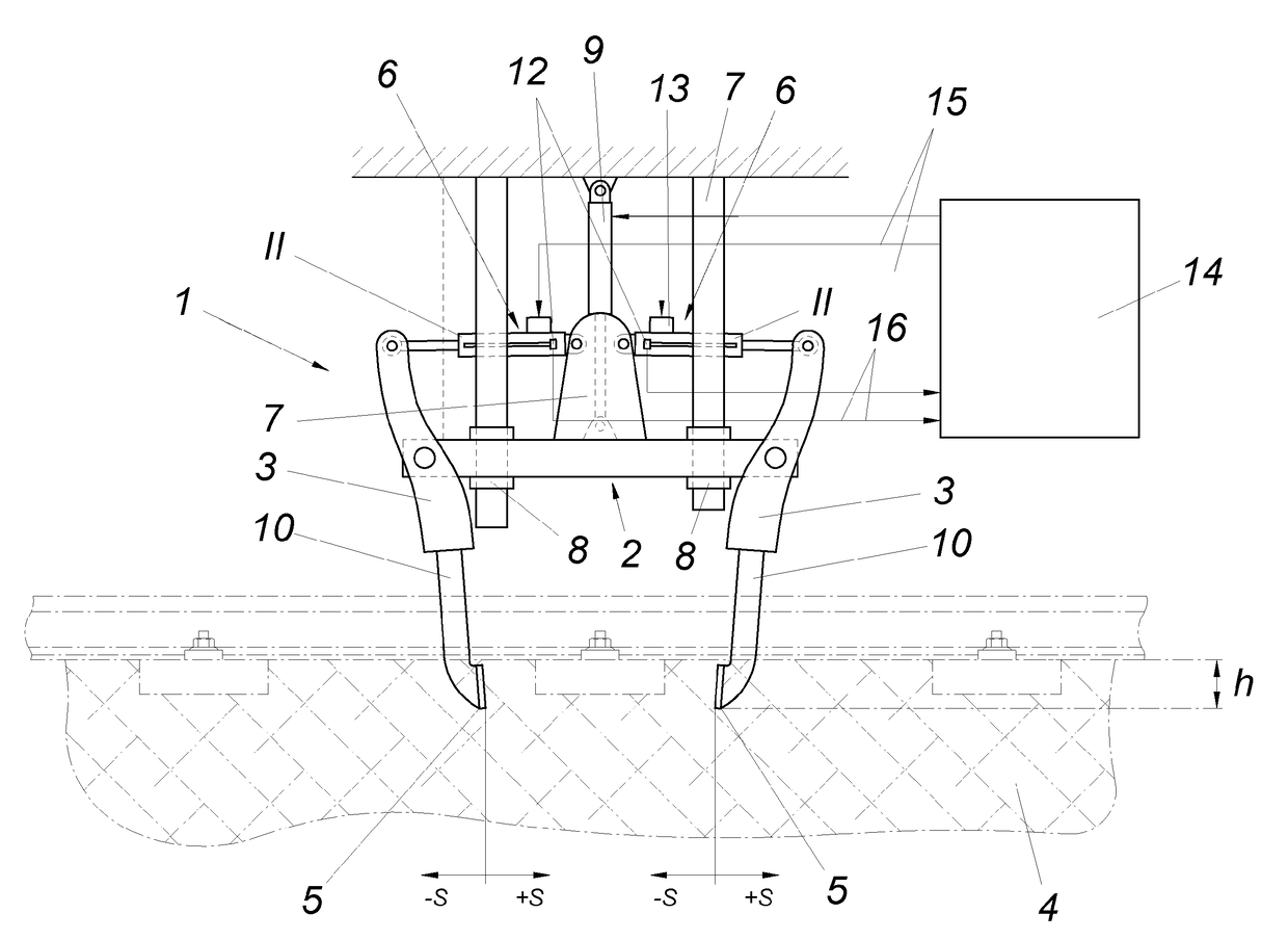
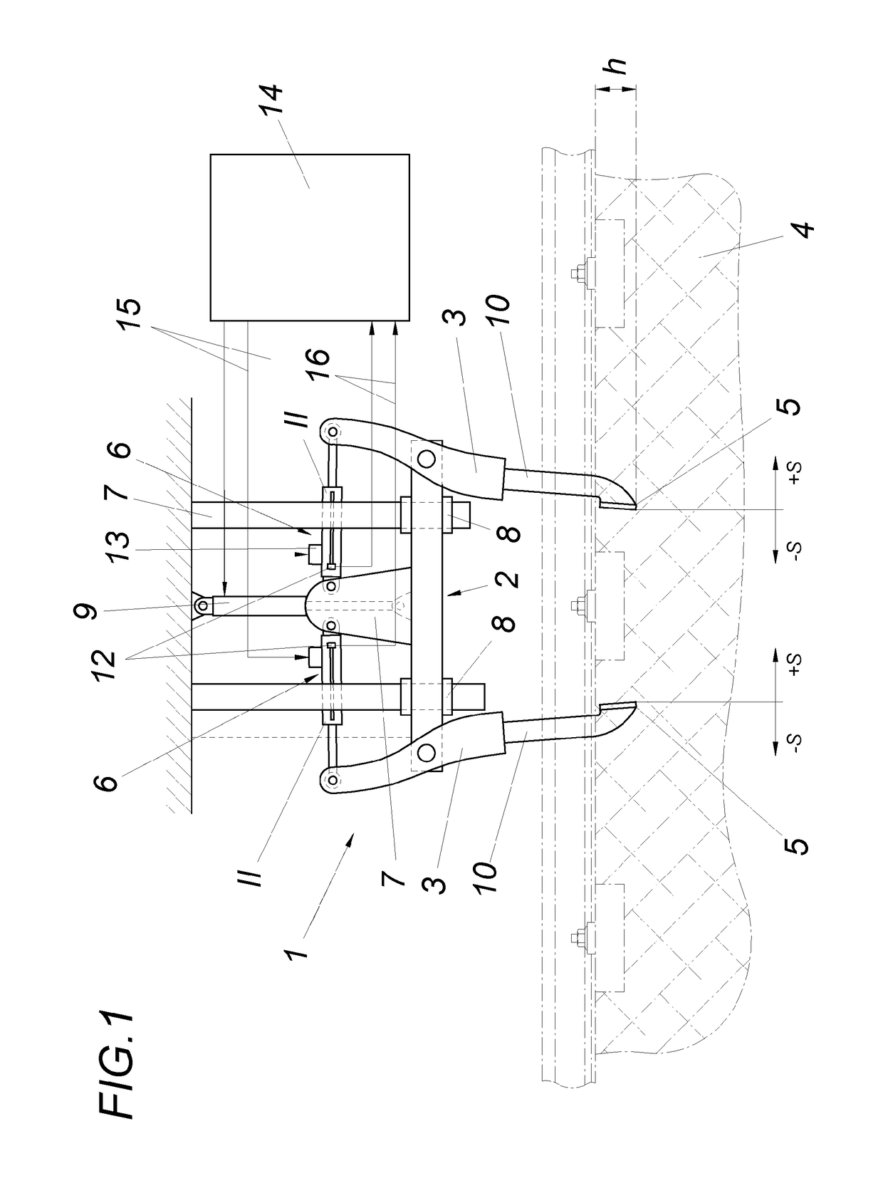
[0019]A tamping assembly 1 for a track tamping machine comprises, inter alia, a pair of tamping tools, which is arranged on a carrier 2 and is designed as a rocker arm, having tamping tools 3, the lower tamping pick ends 5 of which, which are intended to plunge into a ballast bed 4, are drivable in opposite directions using an oscillation drive 6 and can be fed hydraulically toward one another, with a feed distance s. The carrier 2 is guided so it is vertically adjustable in a tamping assembly frame 7 having guides 8 and is displaceable into the desired vertical location using a positioning cylinder 9. The tamping tools 3 are designed as two-armed levers, which are mounted so they are pivotable on the carrier 2. One arm of the respective tamping tool 3 is formed by a tamping pick 10 and a hydraulic cylinder 11 engages on the other arm, which is in turn mounted at the other end on the carrier 2.

[0020]A hydraulic cylinder 11 and a distance sensor 12 for determining the hydraulic cylin...


PUM


Abstract

A tamping assembly for a track tamping machine has a pair of tamping tools arranged on a carrier (2) so it is vertically adjustable in a tamping assembly frame and is designed as a rocker arm, the lower tamping pick ends (5) of which, which plunge into a ballast bed (4), are drivable in opposite directions using an oscillation drive (6) and can be fed hydraulically toward one another. To increase the stability of the tamping assembly, a hydraulic cylinder (11) and a distance sensor (12) for determining the hydraulic cylinder position are associated with each of the tamping tools (3) of a tamping tool pair, wherein the hydraulic cylinders (11) form the feed drive and also the oscillation drive (6) of the tamping tools (3) and the hydraulic cylinders (11) are activated in dependence on the distance sensor signal.

Description

FIELD OF THE INVENTION[0001]The invention relates to a tamping unit for a track tamping machine having a pair of tamping tools, which are guided so they are vertically adjustable in a tamping assembly frame, are arranged on a carrier, and are designed as rocker arms, the lower tamping pick ends of which, which are intended to plunge into a ballast bed, are drivable in opposite directions using an oscillation drive and can be hydraulically fed toward one another.DESCRIPTION OF THE PRIOR ART[0002]Tamping assemblies penetrate the ballast of a track bed using tamping tools in the region between two sleepers (intermediate compartment), in the region of the support of the sleeper in the ballast under the rail, and compact the ballast by way of a dynamic vibration of the tamping picks between the tamping picks, which can be fed toward one another. Tamping assemblies can tamp one, two, or more sleepers in one work cycle (DE 24 24 829 A).[0003]The movements of a tamping assembly comprise the...

Claims


Application Information

Patent Timeline
Patent Type & Authority Patents(United States)
IPC IPC(8): E01B27/16
CPCE01B27/16
Inventor LICHTBERGER, BERNHARD
Owner HP3 REAL GMBH
Why Eureka
Try Eureka