Throttle valve

a technology of throttle valve and valve body, which is applied in the direction of valve details, valve housings, valve arrangements, etc., can solve the problems of reducing the ability of the throttle valve to effectively control the air flow, unstable pressure within the processing chamber, and affecting so as to improve the stability of the pressure of the processing chamber, prevent the degree of opening of the throttle valve, and increase the life of the throttle valv

Active Publication Date: 2018-05-01
VANGUARD INTERNATIONAL SEMICONDUCTOR CORPORATION
View PDF11 Cites 22 Cited by
  • Summary
  • Abstract
  • Description
  • Claims
  • Application Information

AI Technical Summary

Benefits of technology

[0015]Utilizing the throttle valve of the first embodiment of the invention, the first scraper cleans the hollow seal and the body inner wall of the throttle valve body. Therefore, the particles are prevented from being deposited on the hollow seal and the body inner wall. The flow path of the throttle valve would not be barricaded by the particle deposition, and the degree of opening of the throttle valve is prevented from repeatedly being modified. The stability of the pressure of the processing chamber is improved, and the lifetime of the throttle valve is increased.

Problems solved by technology

Volatile contaminants which are maintained in their vapor state under the high temperatures of an active processing chamber can and do undesirably condense on the walls of the cool vacuum piping at some distance from the processing area of the processing chamber, but still within the containment limit of the processing chamber defined by the vacuum valve.
During no-flow conditions, these contaminants can migrate back into the processing part of the chamber to undesirably contribute to its contamination.
Cleaning interferes with normal production processing.
However, pollution in the form of particulate matter is usually deposited on the inner elements of the throttle valve, and this decreases the ability of the throttle valve to effectively control the air flow.
When the particle pollution is deposited on the inner elements of the throttle valve, the stepper motor repeatedly modifies the degree of opening of the throttle valve, causing the pressure within the processing chamber to be unstable, and the lifetime of the throttle valve to decrease.

Method used


Image

  • Throttle valve
  • Throttle valve
  • Throttle valve

Examples


first embodiment

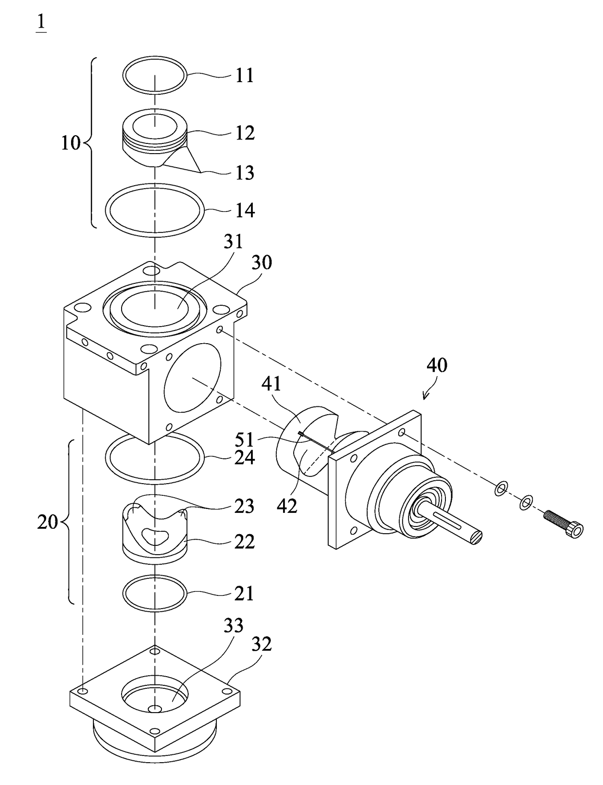
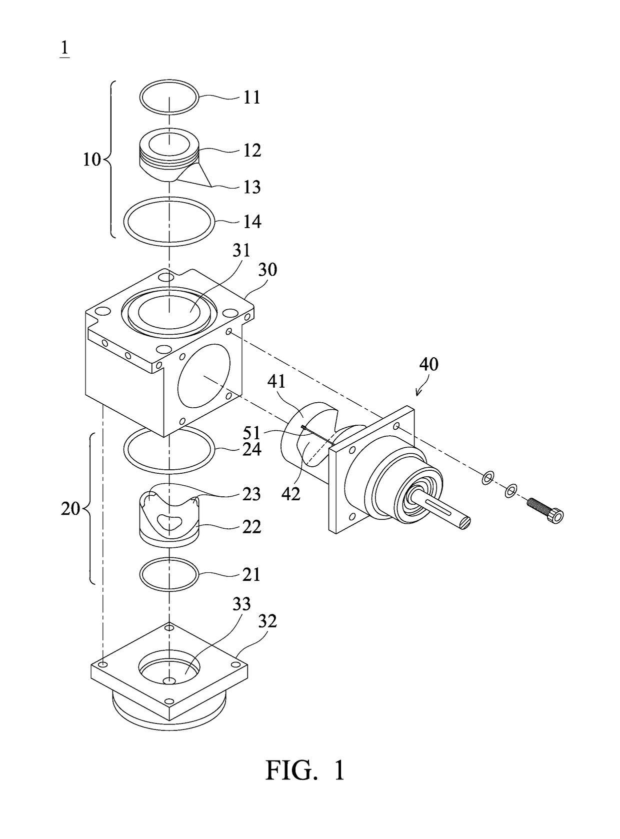
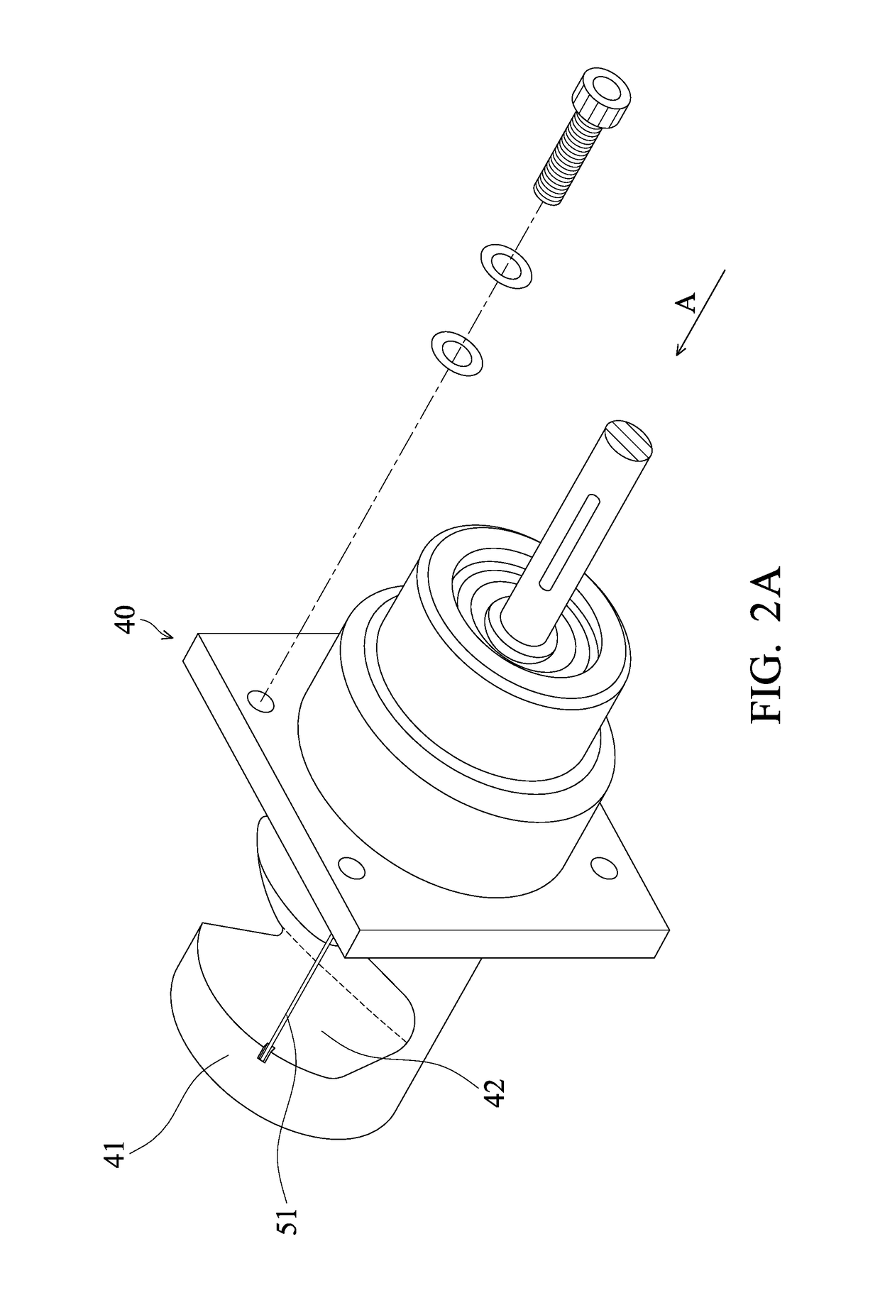
[0025]FIG. 1 shows a throttle valve 1 of the invention. The throttle valve 1 includes a first connection unit 10, a second connection unit 20, a throttle valve body 30, a valve plug unit 40, and a first scraper 51. The first connection unit 10 comprises an O-ring 11, a hollow seal 12 and an O-ring 14. The second connection unit 20 comprises an O-ring 21, a hollow seal 22 and an O-ring 24. The throttle valve body 30 comprises an inlet 31. The valve plug unit 40 comprises a valve plug 41, and a notch 42 is formed on the valve plug 41. The throttle valve body 30 comprises a cover 32, and an outlet 33 is formed on the cover 32. The first scraper 51 is disposed on the valve plug 41.

[0026]With reference to FIG. 1, a flow path is formed in the throttle valve body 30 (from the inlet 31 to the outlet 33). In the embodiment, the flow path is straight, and the inlet 31 and the outlet 51 are located on the same straight line. The valve plug 41 is disposed in the throttle valve body 30. By rotat...

second embodiment

[0032]FIG. 3 shows a throttle valve 2 of the invention. The throttle valve 1 includes a first connection unit 10, a second connection unit 20, a throttle valve body 30, a valve plug unit 40, a first scraper 51 and a second scraper 52. The first connection unit 10 comprises an O-ring 11, a hollow seal 12 and an O-ring 14. The second connection unit 20 comprises an O-ring 21, a hollow seal 22 and an O-ring 24. The throttle valve body 30 comprises an inlet 31. The valve plug unit 40 comprises a valve plug 41, and a notch 42 is formed on the valve plug 41. The throttle valve body 30 comprises a cover 32, and an outlet 33 is formed on the cover 32. The first scraper 51 is disposed on the valve plug 41. The second scraper 52 is disposed on the valve plug 41.

[0033]With reference to FIG. 3, a flow path is formed in the throttle valve body 30 (from the inlet 31 to the outlet 33). In the embodiment, the flow path is straight, and the inlet 31 and the outlet 51 are located on the same straight...


PUM


Abstract

A throttle valve is provided. The throttle valve includes a throttle valve body, a valve plug, a hollow seal and a first scraper. A flow path is formed in the throttle valve body. The valve plug is disposed in the throttle valve body. A notch is formed on the valve plug. By rotating the valve plug, the position of the notch is changed, and the degree of opening of the flow path is modified. The hollow seal is disposed in the throttle valve body. An abutting portion is formed on the hollow seal, and the abutting portion sealably abuts the valve plug. The first scraper is disposed on the valve plug. When the valve plug is rotated, the first scraper abuts the abutting portion to clean the abutting portion.

Description

BACKGROUND OF THE INVENTIONField of the Invention[0001]The present invention relates to a throttle valve, and in particular to a throttle valve prevented from being polluted by particles.Description of the Related Art[0002]The process of depositing layers on a semiconductor Wafer (or substrate) usually involves heating the substrate and holding it a short distance from the source of a stream of deposition (or process) gas flowing towards the substrate. The flowing gas reacts and deposits a layer on the heated substrate.[0003]At some point in the vacuum line between the chamber and the vacuum pump, a vacuum shut-off or throttle valve is typically provided which when closed acts as a limit of the process chamber containment. Volatile contaminants which are maintained in their vapor state under the high temperatures of an active processing chamber can and do undesirably condense on the walls of the cool vacuum piping at some distance from the processing area of the processing chamber, ...

Claims


Application Information

Patent Timeline
Patent Type & Authority Patents(United States)
IPC IPC(8): F16K5/08F16K5/04
CPCF16K5/08F16K5/0464F16K5/0407F16K5/18F16K27/065
Inventor YANG, REUNN-CHANG
Owner VANGUARD INTERNATIONAL SEMICONDUCTOR CORPORATION
Why Eureka
Try Eureka