
Method and system for checking an acoustic transducer

a technology of acoustic transducers and operability, applied in the direction of electrical devices, etc., can solve the problems of only being able to test, disturbing the patient's hearing, and acoustic transducers such as speakers,

Active Publication Date: 2018-05-01
KONINKLJIJKE PHILIPS NV
View PDF9 Cites 2 Cited by
  • Summary
  • Abstract
  • Description
  • Claims
  • Application Information

AI Technical Summary

Benefits of technology

Enables non-intrusive, continuous testing of acoustic transducers, preventing false results and disturbing noise, ensuring reliable audio output in medical devices by using an inaudible test signal and efficient frequency analysis.

Problems solved by technology

Permanent testing of acoustic transducers, such as speakers, during normal operation faces several problems.
Moreover, due to the operational area of medical devices, any disturbing noise audible to a patient is not acceptable and should be prevented.
However, the test is only possible when no other audio signal (e.g. coming from a medical device) is present at the speaker.
It even stops current audio output and produces audible noise while testing.

Method used


Image

  • Method and system for checking an acoustic transducer
  • Method and system for checking an acoustic transducer
  • Method and system for checking an acoustic transducer

Examples


first embodiment

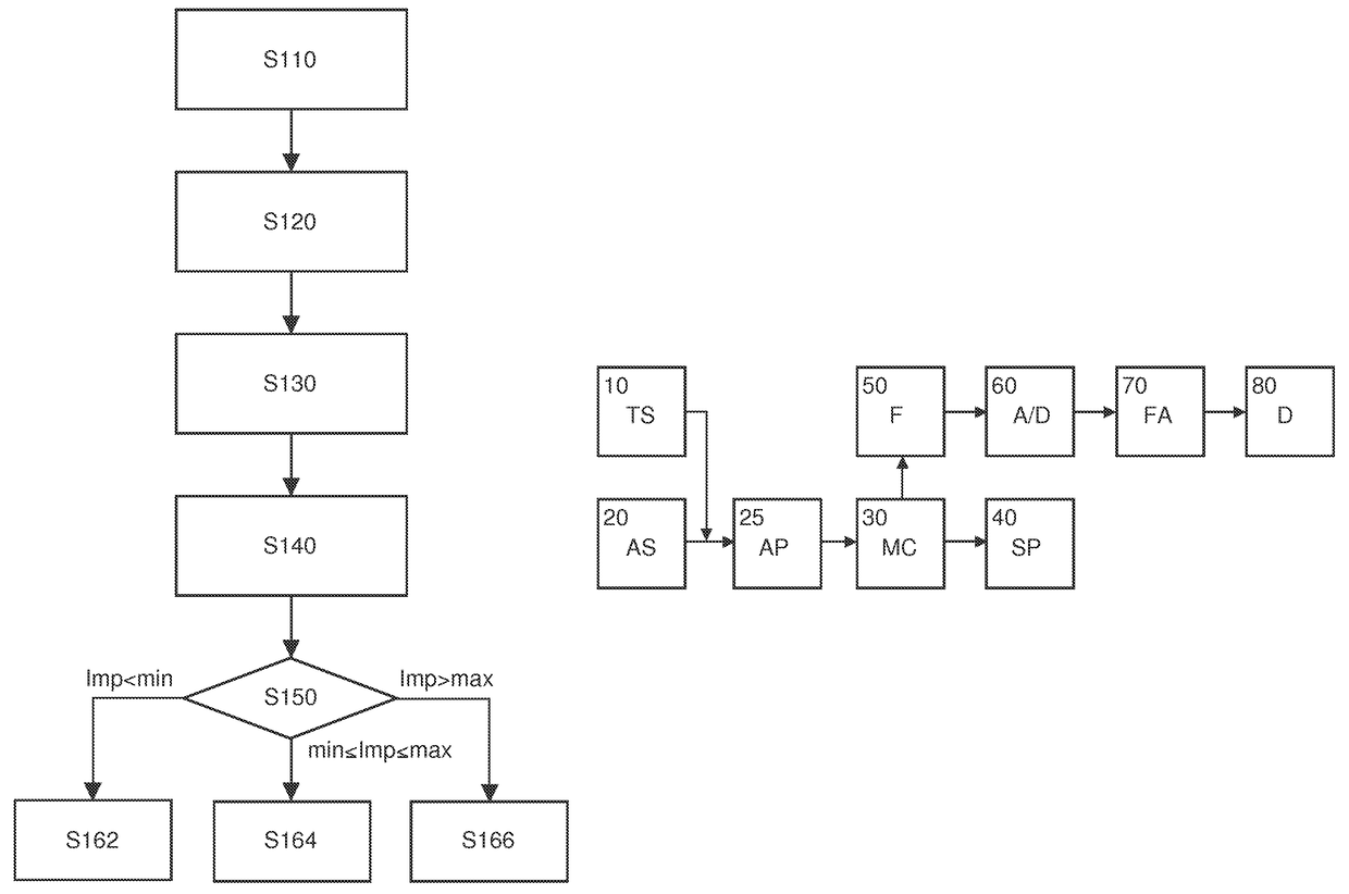
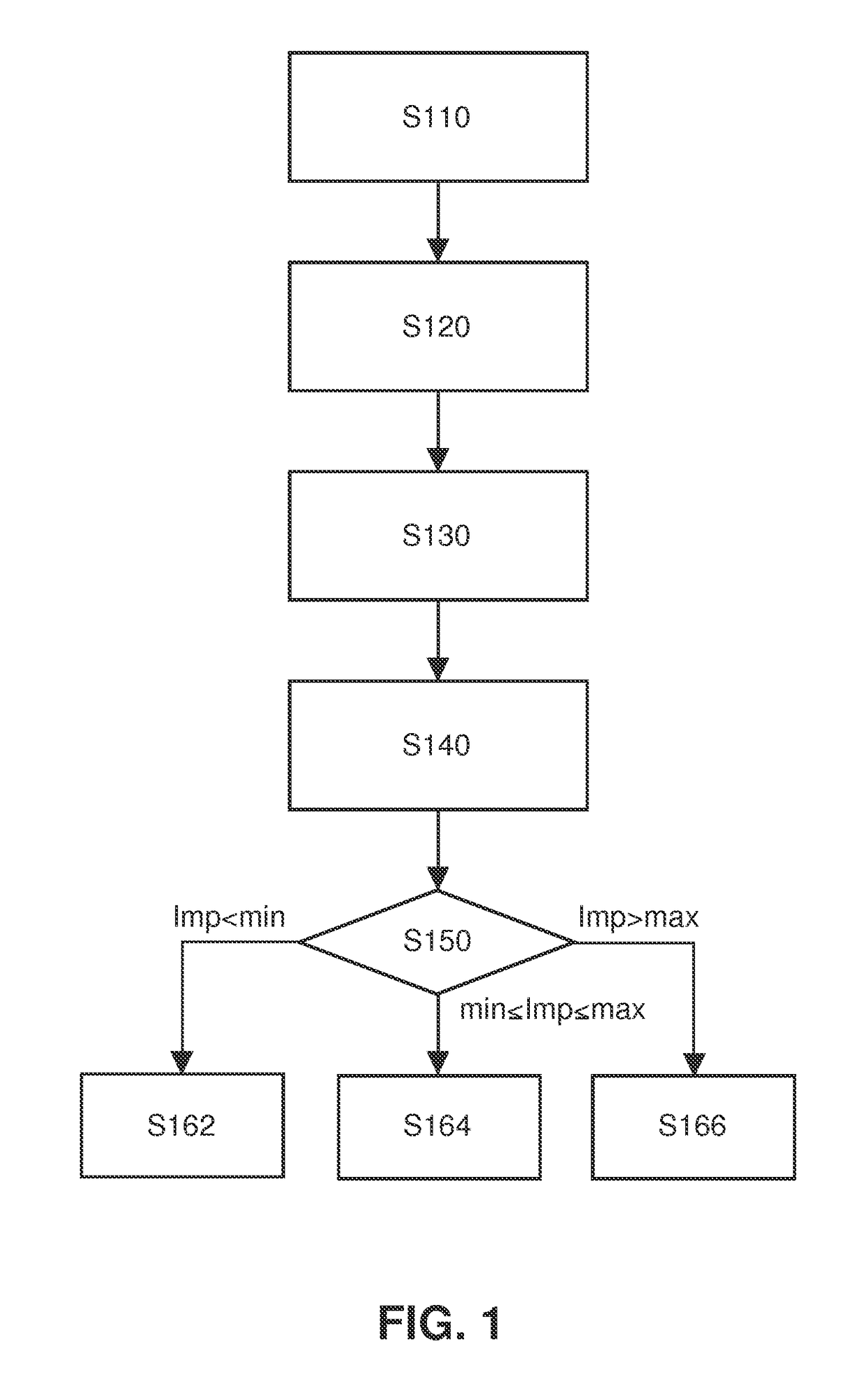
[0022]FIG. 1 shows a flow diagram of a speaker test or audio system checking procedure according to a In step S110, an inaudible permanent test signal is added on top of the normal audio signal of the medical device. Then, in step S120 the alternating current (AC) in the speaker path is measured by deriving and filtering the signal mix consisting of the test signal and the normal audio signal. Then, in step S130, the measured analog signal is converted to a digital signal. In the following step S140, the magnitude of the digital signal at test signal frequency is derived by using the Goertzel algorithm. All other signal parts are ignored by this algorithm. The obtained magnitude is then used in step S150 to decide about the speaker functionality and its electrical connection to the medical device and the functionality of other parts of the audio output system. To achieve this, an impedance is calculated based on the obtained magnitude and is compared with a minimum and maximum resi...

second embodiment

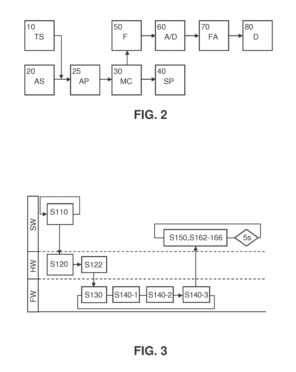
[0025]FIG. 2 shows a schematic block diagram of a speaker test or audio checking system or device according to

[0026]During normal operation, a test signal generator (TS) 10 which may be implemented by a central processing unit (CPU) always outputs a test signal (e.g. a 4 Hz or 25 kHz sinusoidal signal at 50 mVP). Since the frequency of the test signal is in the inaudible range, it is not audible for a human being. Furthermore, generation of the test signal is turned on with the checking system or monitor and will be turned off when the checking system or monitor is turned off. Thereby, any disturbance by the switching of the test signal can be prevented and permanent testing is possible. The normal audio signal is generated from an audio source (AS) 20 which may be part of the medical device which uses the common audio path (AP) 25 and a speaker (SP) 40 as an audio output. If an audio signal is generated by the audio source 20, the test signal will be added to this audio signal. The...


PUM


Abstract

An acoustic transducer and audio system are checked for operability continuously during operation without interfering with their operation. An inaudible test signal is added on top of a normal audio signal of an electronic device. A mix of the test signal and the normal audio signal is converted to a digital signal which is processed by a type of Fourier transformation, e.g. the Goertzel algorithm, to derive the magnitude of the digital signal at the test signal frequency. The derived magnitude is used to gain knowledge about the functionality of the acoustic transducer and its electrical connection to the electric device, as well as a common audio path.

Description

CROSS REFERENCE TO RELATED APPLICATIONS[0001]This application is a national filing of PCT application Serial No. PCT / IB2013 / 052630, filed Apr. 2, 2013, published as WO 2013 / 153484 A1 on Oct. 17, 2013, which claims the benefit of U.S. provisional application Ser. No. 61 / 622,124 filed Apr. 10, 2012, which is incorporated herein by reference.FIELD OF THE INVENTION[0002]The invention relates to a method and a system for checking operability of an audio output system, in particular an acoustic transducer, e.g. a speaker of an electronic device.BACKGROUND OF THE INVENTION[0003]Permanent testing of acoustic transducers, such as speakers, during normal operation faces several problems. Especially in medical devices (e.g. a portable or a stationary patient monitors) with their alarming function, the audio output of such medical devices must not be influenced or even stopped while testing the functionality of an incorporated speaker. It is desirable that audio signals (e.g. alarm tones) are n...

Claims


Application Information

Patent Timeline
Patent Type & Authority Patents(United States)
IPC IPC(8): H04R29/00
CPCH04R29/001
Inventor GAISER, YVONNEBAUER, KURT
Owner KONINKLJIJKE PHILIPS NV
Learn More