Supercharge Your Innovation With Domain-Expert AI Agents!

Method for producing stabilizer and heating device

a technology of stabilizer and heating device, which is applied in the direction of heat treatment apparatus, manufacturing tools, furnaces, etc., can solve the problems of high production cost, difficult production, and difficult heating of the entire cross sectional area, and achieve the effect of uniform heating of the entire hollow member

Active Publication Date: 2018-05-15
NHK SPRING CO LTD
View PDF14 Cites 0 Cited by
  • Summary
  • Abstract
  • Description
  • Claims
  • Application Information

AI Technical Summary

Benefits of technology

This approach allows for uniform heating of the entire hollow member to the necessary temperature for heat treatment, preventing overheating and melting, and ensuring consistent material properties across varying cross-sectional areas.

Problems solved by technology

In the above three documents, since the member includes a portion at which the diameter of the material varies along the central axis, it is difficult to produce and the production cost thereof is high.
As a result, it is difficult to heat the entirety of the cross sectional area varying hollow member uniformly until the temperature necessary to perform quenching.

Method used


Image

  • Method for producing stabilizer and heating device
  • Method for producing stabilizer and heating device
  • Method for producing stabilizer and heating device

Examples


Embodiment Construction

(1) Structure of Stabilizer

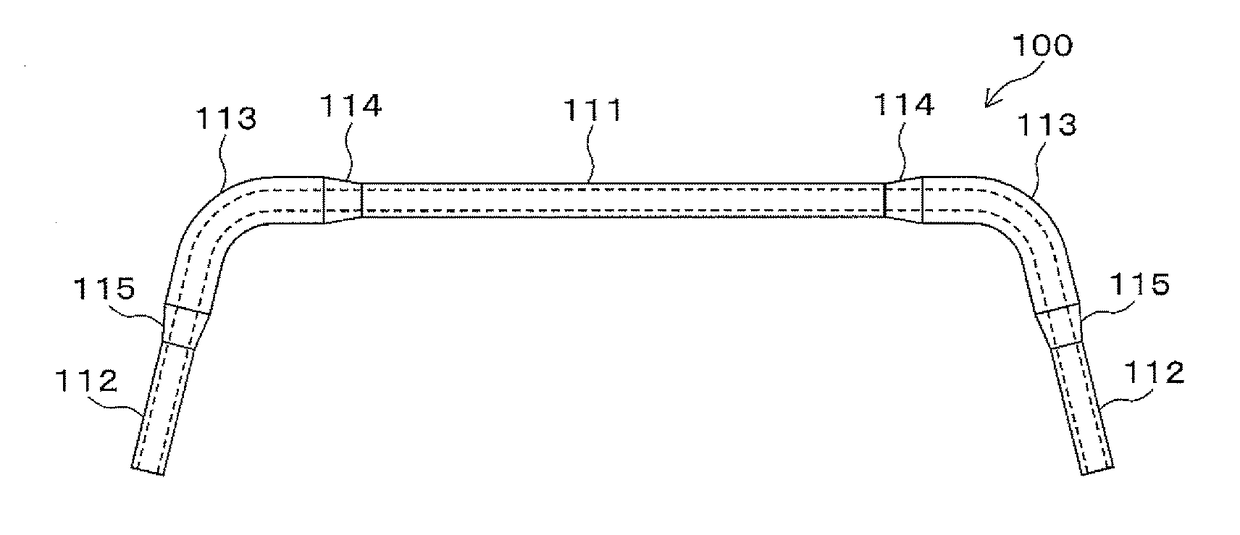
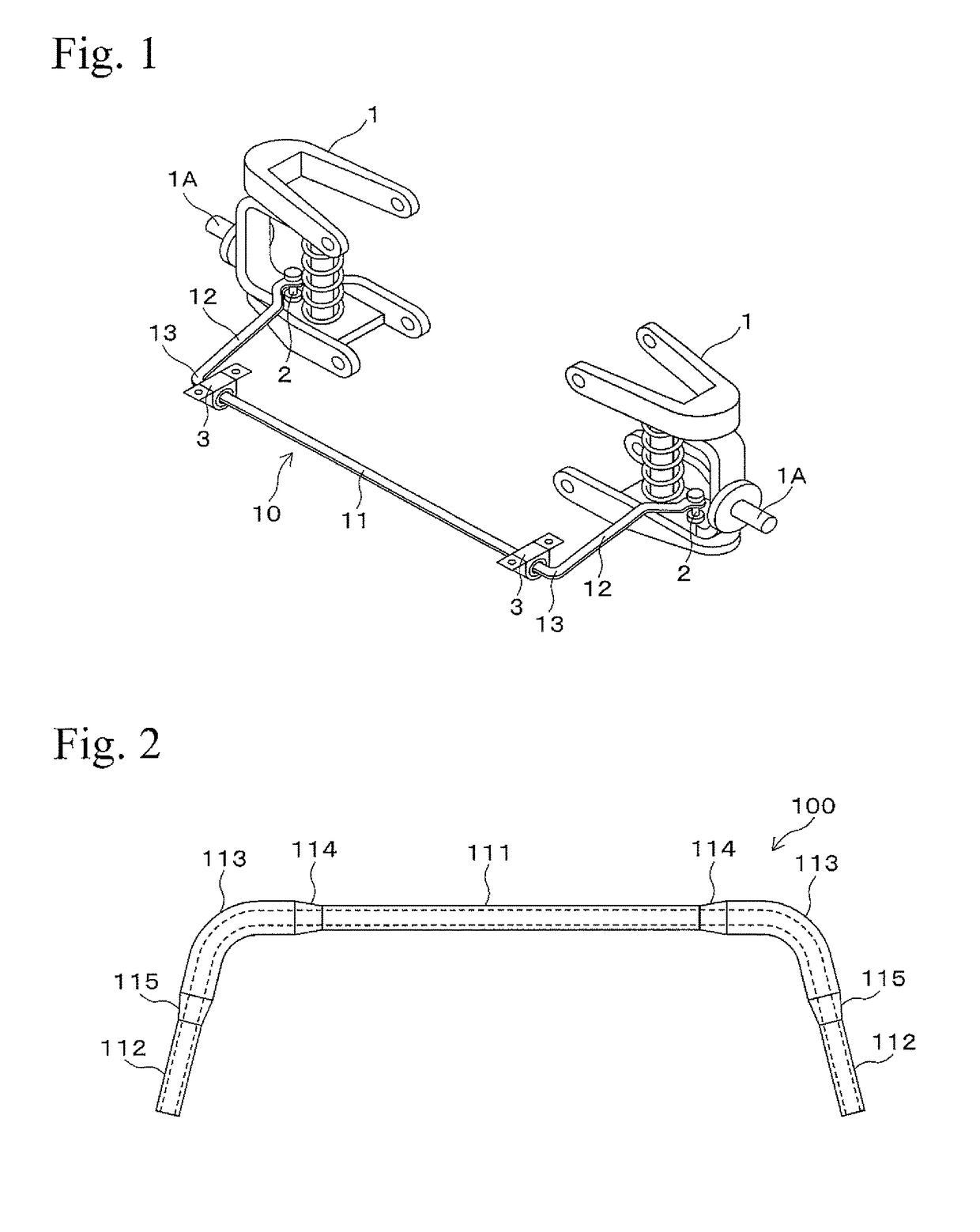
[0031]Hereinafter, one Embodiment of the present invention is explained with reference to the drawings. For example, a stabilizer 100 shown in FIG. 2 is a hollow stabilizer having approximately the shape of the letter U including a torsion part 111, arm parts 112, and shoulder parts 113. The torsion part 111 and the shoulder part 113 are connected by a cross section varying part 114, and the arm part 112 and the shoulder part 113 are connected by a cross sectional varying part 115.

[0032]In the stabilizer 100, the inner diameter is set constant, and the outer diameter is set so that it varies depending on location. It should be noted that the dotted line in FIG. 2 indicates an inner circumferential surface. The torsion part 111 and the arm parts 112 have a primary outer diameter, the shoulder parts 113 have a secondary outer diameter, and the secondary outer diameter is set to be larger than the primary outer diameter. In this way, the torsion part 111 and ...


PUM

PropertyMeasurementUnit
temperatureaaaaaaaaaa
electric currentaaaaaaaaaa

Abstract

A method for producing a stabilizer and a heating device allows the entirety of a hollow member to be uniformly heated to a temperature necessary for heat treatment, even in a case in which a cross section varying hollow member is used as the starting material. In a preliminary heating process, energizing heating is performed between electrodes, which are arranged at cross section varying parts at both ends of large cross sectional area part, which can be heated. In an entire heating process, by performing energizing heating between electrodes, which are arranged at both ends of the cross section varying hollow member, the latter can be heated. In the preliminary heating process, it is desirable to perform energization heating at a part having a cross sectional area ratio of 90% or more with respect to the part having a large cross sectional area in the cross section varying part.

Description

TECHNICAL FIELD[0001]The present invention relates to a method for producing a stabilizer that is constructed of a hollow member having a portion in which a cross sectional area thereof varies along the central axis, and relates to a heating device, and in particular, relates to improvements in heating techniques for heating treatment.BACKGROUND ART[0002]A stabilizer that is used for vehicles such as automobiles is a device for maintaining roll rigidity of the vehicles. FIG. 1 is a perspective view showing a construction of a stabilizer that is connected to a suspension device of a car. The stabilizer 10 includes a torsion part 11, an arm part 12, and a shoulder part 13, for example, and is formed approximately in the shape of the letter U. In the stabilizer 10, the torsion part 11 is attached to a car body (not shown) via bushes 3, and top portions of the arm part 12 are connected to the suspension devices 1 via stabilizer links 2. It should be noted that a tire (not shown) is atta...

Claims


Application Information

Patent Timeline
Patent Type & Authority Patents(United States)
IPC IPC(8): B60G21/055C21D9/00C21D1/40C21D9/08H05B3/02
CPCB60G21/055C21D1/40C21D9/0068H05B3/023C21D9/08B60G2206/80B60G2206/427H05B3/0004
Inventor KURODA, SHIGERUOHMURA, SHUJI
Owner NHK SPRING CO LTD
Features
  • R&D
  • Intellectual Property
  • Life Sciences
  • Materials
  • Tech Scout
  • Unparalleled Data Quality
  • Higher Quality Content
  • 60% Fewer Hallucinations
Learn More