Apparatus, method, and system for lighting fixture cooling

a technology for lighting fixtures and cooling devices, applied in lighting and heating devices, instruments, lighting support devices, etc., can solve the problems of capital and operating costs of such subsystems over their normal operating life, and achieve the effect of reducing capital costs, justified costs of air cooling subsystems, and reducing capital and operating costs

Inactive Publication Date: 2018-05-15
MUSCO
View PDF16 Cites 2 Cited by
  • Summary
  • Abstract
  • Description
  • Claims
  • Application Information

AI Technical Summary

Benefits of technology

[0011]One embodiment according to the present invention uses air cooling to reduce the temperature of wide-area lighting fixtures. A small blower or fan (e.g., on the order of ⅓ horsepower) is installed with its output directed into a hollow lighting support pole. Air distribution is through the pole and either coaxially through the fixture mounts, or through appropriate ducting from the pole to the fixtures. Air is directed through the fixtures or to the heat sink on the back side of fixtures. Power usage for the blower would be calculated and energy cost for the blower versus potential power savings for the fixtures compared, with optimum values calculated based on the needs of the project. For the example of model XP-G LEDs, available from Cree, Durham, N.C., USA, efficacy increases on the order of 10-15% should be achievable, resulting in cost savings of tens or hundreds of dollars. This method would ideally be applied to sports lighting applications, which typically have many high wattage fixtures mounted on each pole. This allows the cost of the blower and its energy draw to be allocated to many fixtures. Further, since increasing total light output per fixture is very beneficial for sports lighting, and since a major limiting factor in using LEDs in sports lighting is temperature rise due to increased power, significant cost savings might result. Conversely, for other wide-area lighting (e.g., parking lot lighting, street lighting, etc.), while the cost savings resulting from the increased energy efficiency attributed to air cooling might not in itself be enough to make air cooling economically advantageous, air cooling might increase expected LED life enough to make air cooling economically feasible as well.

Problems solved by technology

While the use of LEDs in wide-area or other lighting applications typically employing HID or other traditional light sources seems promising (e.g., due to the longevity of LEDs), one must consider an issue previously unaddressed (in many cases) for lighting systems using traditional light sources: heat management.
Some considerations include, but are not limited to, establishing a source of pressurized air mounted below the fixtures on an elevating structure, creating air pathways to the fixtures elevated on the structure, and capital and operating costs for such a subsystem over its normal operating life.

Method used


Image

  • Apparatus, method, and system for lighting fixture cooling
  • Apparatus, method, and system for lighting fixture cooling
  • Apparatus, method, and system for lighting fixture cooling

Examples


embodiment 1

B. Exemplary Method and Apparatus Embodiment 1

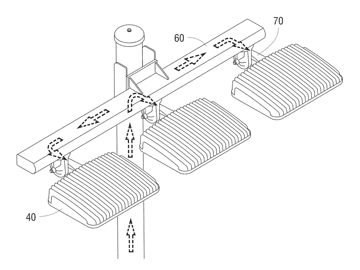
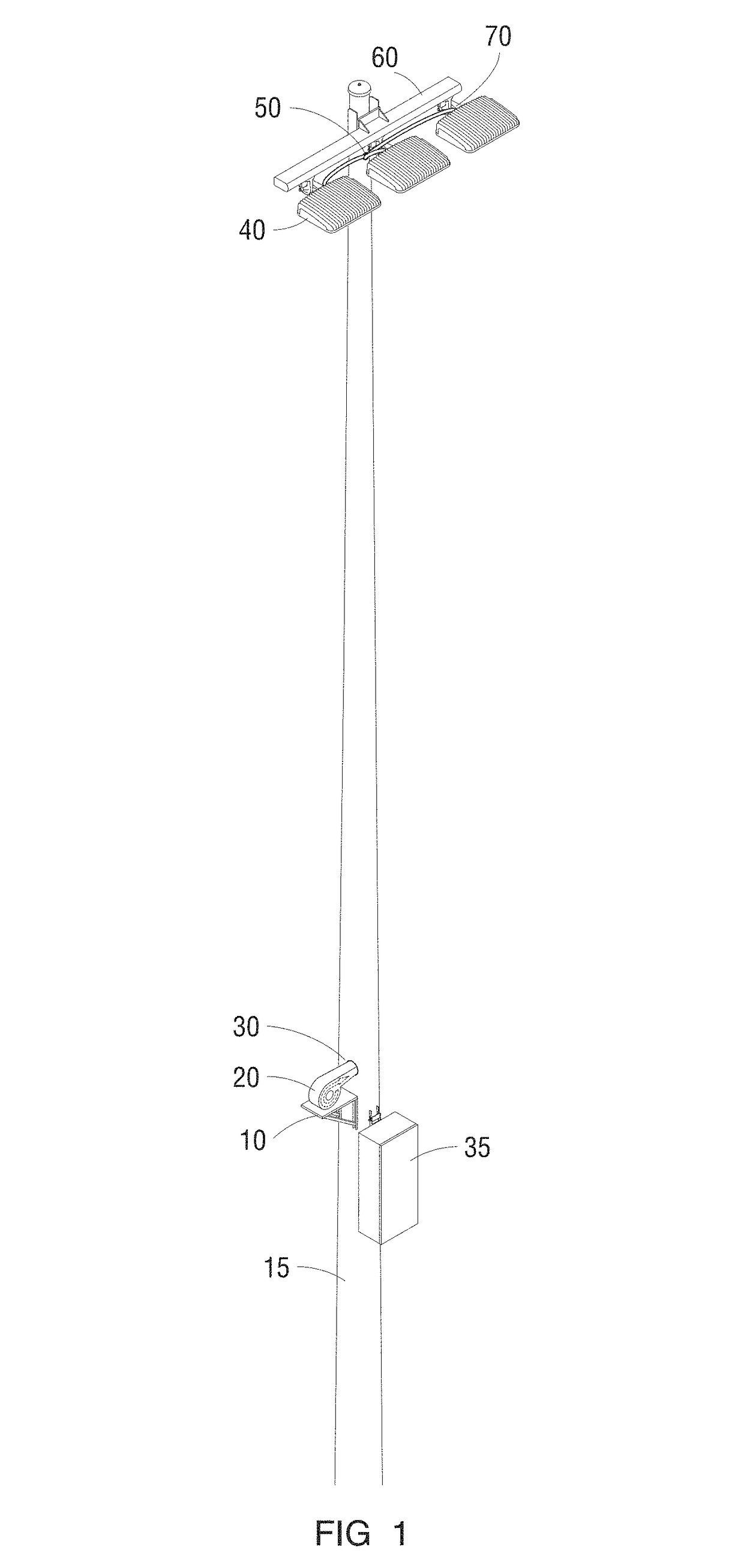
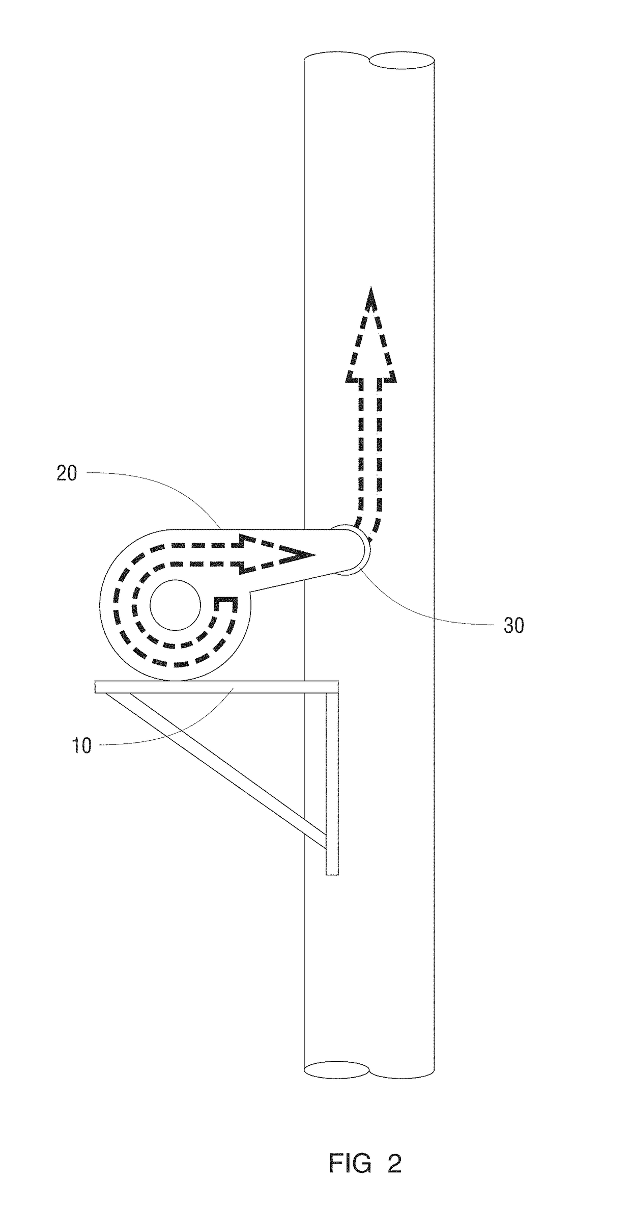
[0027]In a first embodiment, pole 15, FIG. 1 elevates light fixtures 40 some distance in the air, on the order of (for example) 50 feet or more. One example of light fixtures 40 are model STR-LWY-15-HT available commercially from BetaLED, Sturtevant, Wis., USA. Another example of light fixtures 40 are those disclosed in U.S. patent application Ser. No. 12 / 626,095, incorporated by reference herein and commonly owned by the assignee of the present application. An example of pole 15 is model LSS50A available from Musco Sports Lighting, Oskaloosa, Iowa, USA, which is essentially a hollow galvanized steel tapered pole of either one piece or multiple slip-fit sections. Pole 15 presents a continuous air pathway from its bottom to top. A typical fifty foot tall pole of this nature has a largest outside diameter of approximately 10 inches at its bottom (approximately 79 square inches cross-sectional area), and approximately 6 inches smallest outs...

embodiment 2

C. Exemplary Method and Apparatus Embodiment 2

[0033]FIG. 4 illustrates a second embodiment having a pole 15, blower 20, opening 30, and LED fixture with heat sink 90. Arrows 25 indicate airflow through the pole and fixture. As is illustrated in FIG. 4, airflow through pole 15, and then across a mounting interface 45 (e.g., as may be appropriate for a non-adjustable or static mounting situation), can provide a direct, continuous air path to the inside of a fixture and the proximate edge of heat sink 90. That air can be directed through and across heat sink 90 and out some type of vent at the distal edge of heat sink 90 so to provide an exhaust for the airflow. U.S. patent application Ser. No. 12 / 626,095 and Ser. No. 12 / 623,875, now U.S. Pat. No. 8,651,704, provide some examples of airflow paths.

D. Options & Alternatives

[0034]As can be appreciated, the foregoing detailed description gives but a few examples of apparatus and methods according to the present invention. Variations obviou...


PUM


Abstract

A high-intensity LED lighting system is presented whereby one or more LED lighting fixtures are affixed to an elevating structure, the elevating structure having a substantially continuous internal pathway. Said pathway can be used as a conduit or duct for pressurized air which is introduced at or near the bottom of the elevating structure and forced upwardly toward the lighting fixtures so to provide cooling of one or more components of the lighting fixtures so to, ultimately, improve the efficacy of the LEDs contained therein. A method of designing lighting systems, including analysis of whether or not to add air cooling to increase light source efficiency is also disclosed.

Description

CROSS-REFERENCE TO RELATED APPLICATIONS[0001]This application is a continuation application of U.S. Ser. No. 13 / 791,941 filed Mar. 9, 2013 (now U.S. Pat. No. 9,028,115) which claims priority under 35 U.S.C. § 119 to provisional U.S. application Ser. No. 61 / 645,870 filed May 11, 2012, herein incorporated by reference in its entirety.I. BACKGROUND OF THE INVENTION[0002]In the field of sports and wide-area lighting, manufacturers are attempting to find ways to make the use of light-emitting diodes (LEDs) competitive where high-intensity discharge (HID) lighting has traditionally been dominant. LEDs can be made more competitive by increasing their lumen output, improving efficacy (lumens per watt), increasing longevity, and reducing cost. Thus, any technology that has the potential to improve on one or more of these factors is desirable in the lighting industry.[0003]Certain techniques for improving individual factors are well known in the industry; however, improving one factor may dim...

Claims


Application Information

Patent Timeline
Patent Type & Authority Patents(United States)
IPC IPC(8): F21V29/67G06Q10/06F21V29/70F21V21/22
CPCF21V29/673F21V29/70F21V21/22G06Q10/06315F21Y2101/02F21S8/086F21W2131/105F21Y2115/10F21Y2101/00G06F30/00
Inventor GORDIN, MYRON
Owner MUSCO
Why Eureka
Try Eureka