Wire label with carrier

a carrier and wire technology, applied in the field of wire labels, can solve the problems of distorted images, bulky carrier strips, difficult to remove labels, etc., and achieve the effect of improving the removal of wire labels

Active Publication Date: 2018-05-29
HELLERMANNTYTON CORP
View PDF44 Cites 0 Cited by
  • Summary
  • Abstract
  • Description
  • Claims
  • Application Information

AI Technical Summary

Benefits of technology

[0010]The present invention discloses a carrier strip for wire labels used in printing machines and assemblies and a method for manufacturing the carrier strip. The carrier consists of a first and second backing layer adhered to one another, sandwiching an adhesive layer between the two backing layers. Predetermined areas are removed from the second backing layer to thereby expose the adhesive. Portions of the exposed adhesive are further covered by a plurality of cover tabs, which create a series of exposed windows of adhesive. The windows of adhesive are located on opposing sides of the carrier, corresponding to the ends of wire labels placed on the carrier strip. Once the wire labels are placed over the carrier strip, a layer of adhesive tape is placed over the ends of the wire labels, preferably covering any remaining exposed adhesive located in the windows of adhesive and further securing the wire label ends to the carrier strip. The use of cover tabs to create windows of adhesive allows the labels to be secured to the carrier strip with minimal contact with the adhesive. This feature improves removal of the wire labels after printing.
[0011]The present invention also has the advantage of specialized perforations on individual wire labels when individual wire labels are to be multiply printed and divided into multiple, smaller labels. The perforations define a frangible region that comprises both cut portions and points of attachment, where the cut portions sever the wire label completely and the remaining points of attachment serve as the sole connection to an adjacent wire label. The frangible region allows the labels to be secured to one another during printing, yet be easily separated during use.
[0012]The carrier strip layers are preferably made of a polyethylene material, with each of the layers preferably having a thickness of less than 3 mils. The overall thickness of the carrier strip is preferably less than 7 mils, which is a significant improvement over thicknesses of previous carrier strips. The present carrier strip allows for easier feeding and movement within a printing station or assembly, especially when the carrier strip must move over a curved area or corner in the printing assembly. The carrier strip also allows for easier printing on the labels, since the flexibility of the carrier strip will minimize bowing of the labels and the strip. The carrier strip, including the exposed adhesive, combined with the labels, creates a unitary structure that is rigid and supportive for the printing process.

Problems solved by technology

Once applied, the labels are difficult to remove.
Previous designs for carrying out the process utilize carrier strips that are bulky and not adapted for use in different types of printers.
Such carriers tend to be stiff, which may cause the images printed on the markers to be distorted.
Further, the stiff material may not be easily moved through the printer, since the carrier may have to negotiate curves or bends within the assembly.
Likewise, stiffer material is generally more expensive to produce and may need to be wider than necessary so that there is a sufficient area to move and rotate the carrier.
This may require a wider strip, which also adds to the cost of the material needed for producing the carrier strips.
The carrier strip is relatively thick and stiff and may not be easily fed through certain printers.
While this arrangement does provide support for the labels during printing, the arrangement may induce excess adherence of the label ends to the backing layer and thereby hampers facile removal of the printed labels from the backing layer.

Method used


Image

  • Wire label with carrier
  • Wire label with carrier
  • Wire label with carrier

Examples


Embodiment Construction

[0024]Although the disclosure hereof is detailed and exact to enable those skilled in the art to practice the invention, the physical embodiments herein disclosed merely exemplify the invention which may be embodied in other specific structure. While the preferred embodiment has been described, the details may be changed without departing from the invention, which is defined by the claims.

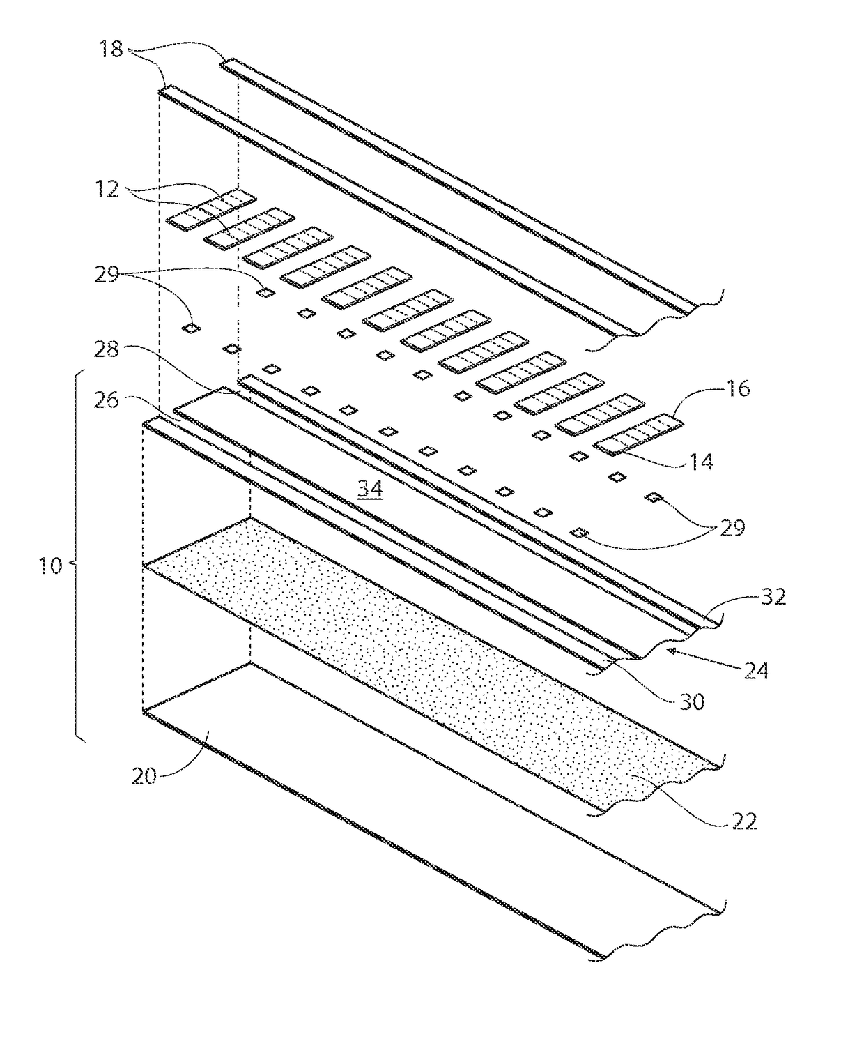
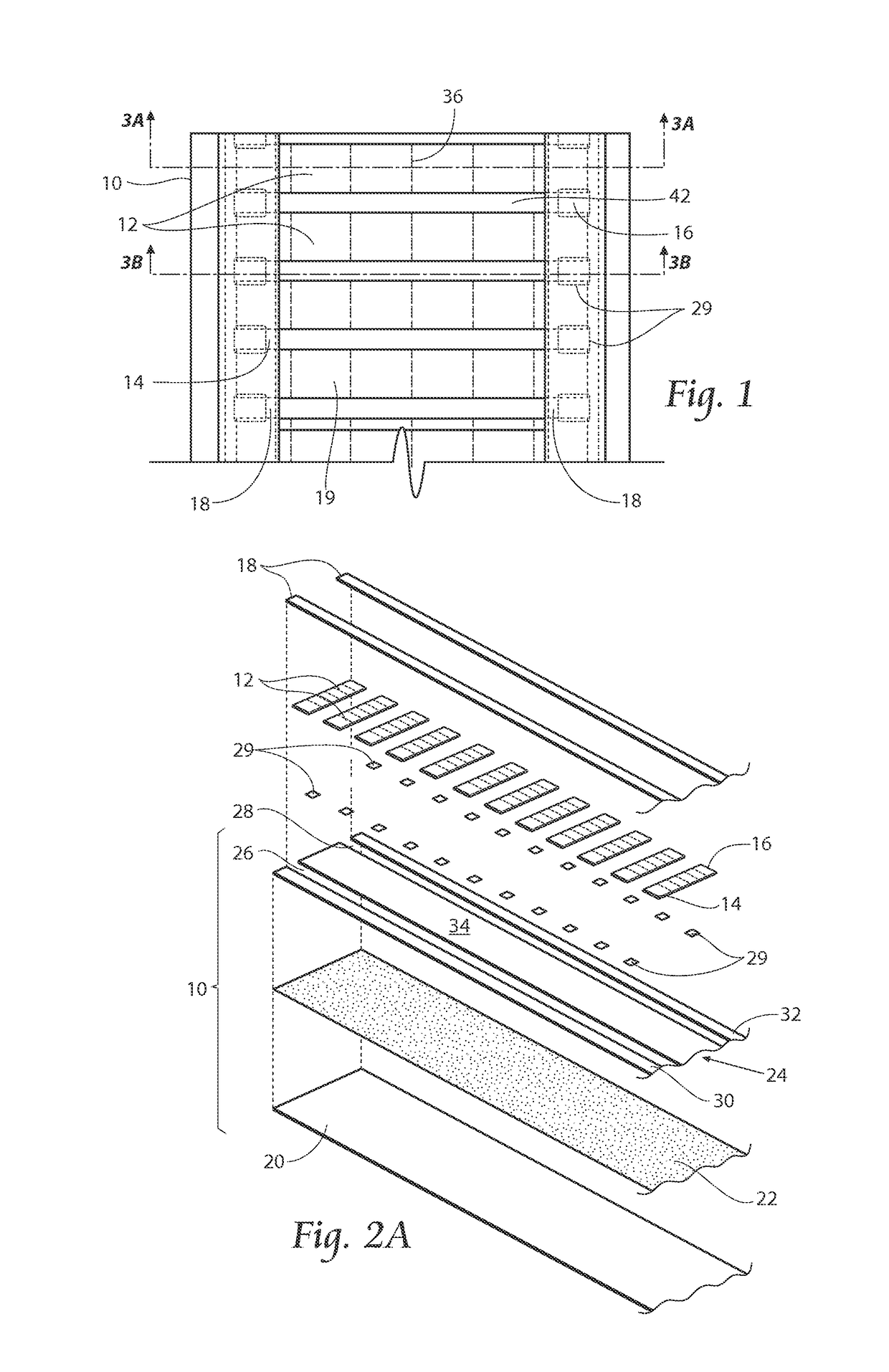
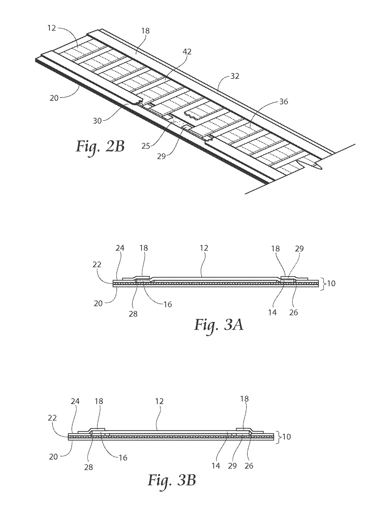
[0025]FIG. 1 shows a top plan view of a carrier strip 10 and a plurality of wire labels 12 to be printed adhered on top of the carrier strip 10. Like parts will be referred to with like reference numerals. The wire labels 12 have a first end 14 and a second end 16 and are arranged substantially laterally to the carrier strip 10. The spacing and size of the wire labels 12 may be of any desired size or orientation. The wire labels 12 are preferably longitudinally spaced from one another at equal intervals. A pair of adhesive tapes 18 is placed respectively over the first end 14 and the second end 16 ...


PUM


Abstract

A label assembly comprised of a carrier strip and a plurality of labels. The carrier strip comprises at least a first backing layer and a layer of adhesive material located over said first backing layer. A second backing layer may be located over said adhesive layer. Predetermined areas are removed from the second backing area to expose the adhesive layer. Cover tabs overlay portions of the exposed adhesive layer with the labels being removably adhered to the carrier strip on the remaining exposed adhesive layer. The labels may be provided with frangible regions for partitioning the wire label. The frangible regions include both severed portions and points of attachment.

Description

RELATED APPLICATION[0001]This application claims the benefit of U.S. Provisional Patent Application Ser. No. 61 / 987,258, filed 1 May 2014.BACKGROUND OF THE INVENTION[0002]The present invention relates to labeling devices, and, more specifically, to labeling devices that are used in connection with electronic printing devices.[0003]In certain devices or equipment, such as airplanes, boats, computer networks or equipment that contains many wires, cables, or other items that may either get easily tangled or confused with other similar items, it is necessary to label the wires, cables or groups of cables of wires. Tags and marker assemblies have been designed to form labels for such uses. Heat shrink technology has been employed in making these markers and tags thereby permitting easy installation. Once applied, the labels are difficult to remove.[0004]Generally, a carrier strip of material containing a plurality of markers is fed through a machine, whereby the markers will pass through...

Claims


Application Information

Patent Timeline
Patent Type & Authority Patents(United States)
IPC IPC(8): B65C9/00G09F3/00
CPCG09F3/0295B65C9/0006Y10T156/14Y10T156/1052B65C2009/009
Inventor BROWN, JAMES T.KLAUS, BROCK S.PETERSEN, JAMES A.
Owner HELLERMANNTYTON CORP
Why Eureka
Try Eureka