Keycap and manufacturing method thereof

a manufacturing method and keycap technology, applied in the field of keycaps, can solve the problems of reducing the product yield of keycaps, affecting the production efficiency of keycaps, and causing non-uniform thickness of protection layers, so as to reduce production time, reduce cost, and reduce contamination.

Active Publication Date: 2018-05-29
DARFON ELECTRONICS CORP
View PDF9 Cites 1 Cited by
  • Summary
  • Abstract
  • Description
  • Claims
  • Application Information

AI Technical Summary

Benefits of technology

[0010]In view of the prior arts, it is an object of the present invention to provide a method of manufacturing keycaps, wherein the surface of the keycap can be selectively covered; in comparison with the prior arts, the method of the present invention has the advantages of reduced production time, lower cost, less contaminants. The keycaps manufactured by the method of the present invention can bring a smooth touch to the user without causing the light leakage that is commonly occurred in the lighting keyboard.
[0014]In an embodiment, the step (c) further includes (c1) adjusting a difference in gas pressure above a top surface and below a bottom surface of the first film. In an embodiment, each of the plurality of positioning units of the first jig has a through hole, and the step (c1) includes (c11) providing a pumping jig including a plurality of gas holes, the pumping jig drawing gas through the gas holes; and (c12) disposing the first jig on the pumping jig to simultaneously draw gas through the through holes from the spaces of the keycaps to reduce the gas pressure under the first film.
[0023]In comparison with the prior arts, the method of the present invention is an eco-economic process, which processes all keycaps of one keyboard at one time and reduces the use of spray coating process to reduce environmental pollution, and has the advantages of selectively covering the keycap as desired and cost-reduction. The keycap manufactured by the method of the present invention can provide the user with a continuous, smooth touch and effectively prevents the light leakage for the lighting keyboard.

Problems solved by technology

Such a forming process is time-consuming.
Especially when multiple layers of ink are employed, the process variation is increased, decreasing the product yield of the keycaps.
In addition, if the protection layer is formed by spray coating, the protection layer will cover all exposed portions of the keycap, resulting in waste and non-uniform thickness of the protection layer caused by the spraying angle.
If the protection layer is formed by the printing technique, the protection layer will cover only the top face of the keycap and cannot extend to the side face of the keycap (i.e. skirt of the keycap), making the user feel uneven touch during operation and affecting the input smoothness.
Consequently, the spray coating or the printing technique cannot form a selective protection layer.
However, the protection layer cannot be formed by the IMR technique, and the keyboard usually includes multiple keycaps of different sizes which cannot be formed by injection molding in the same mold.
That is, the keycaps of different sizes cannot be formed by the injection molding at the same time.
Moreover, due to the restriction of the IMR technique, the gap between the cavities for accommodating the keycaps must be large enough, reducing the number of keycaps of the same size that can be processed by one mold, thus requiring more films and increasing the cost.
Moreover, for the IMR technique, the process involves the steps of releasing the upper mold and the bottom mold; thus the bottom face of the skirt cannot be covered (i.e. barb-like covering).
Consequently, the ink layer on the lower edge of the skirt will exhibit a zigzag or irregular shape, resulting in severe light leakage of the lighting keyboard.

Method used


Image

  • Keycap and manufacturing method thereof
  • Keycap and manufacturing method thereof
  • Keycap and manufacturing method thereof

Examples


Embodiment Construction

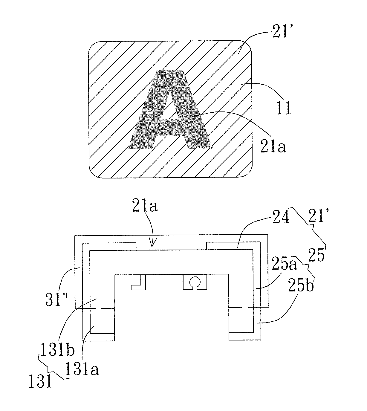
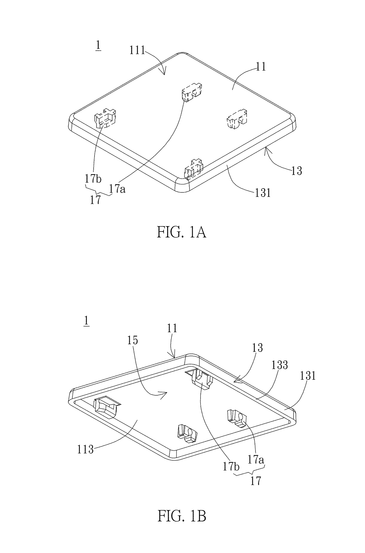
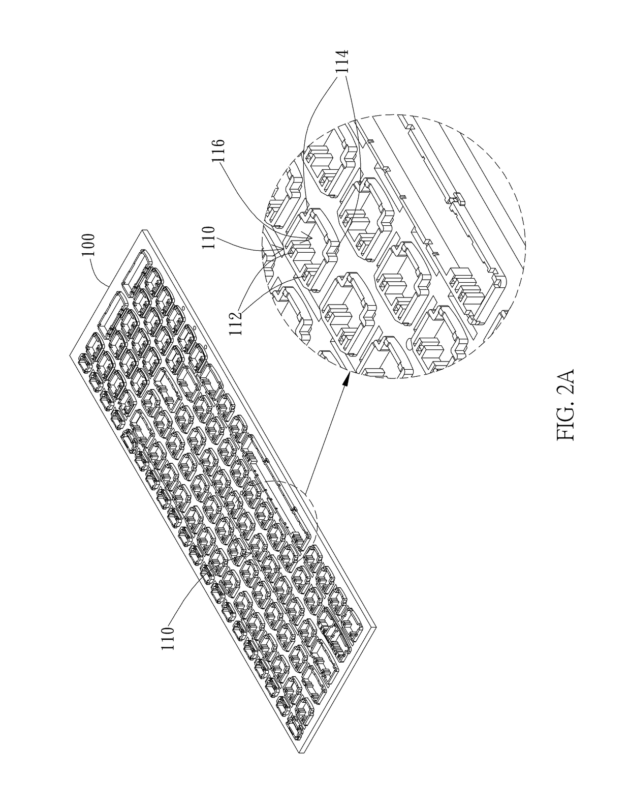
[0043]According to an embodiment of the present invention, a keycap and a manufacturing method thereof are provided, wherein the method can manufacture a plurality of keycaps for corresponding keyswitches of a keyboard product in a batch so as to simplify the manufacturing procedure and cost. The keyboard product can be a commercial keyboard or a keyboard module to be mounted on an electronic device. In the invention, as shown in FIGS. 1A and 1B, the keycap 1 formed by injection molding includes a top 11 and a skirt 13, wherein the top 11 has an upper surface 111 and a lower surface 113. The skirt 13 is surroundingly connected to at least a portion of periphery of the top 11 and includes a side face 131 and a bottom face 133. The top 11 and the skirt 13 together define a space 15 under the keycap 1. In the invention, the top 11 is preferably a quadrilateral, but not limited thereto. It is noted that the quadrilateral top 11 of FIG. 1A is an exemplarily embodiment, the top of the key...


PUM

PropertyMeasurementUnit
thicknessaaaaaaaaaa
heightaaaaaaaaaa
timeaaaaaaaaaa

Abstract

A method of manufacturing keycaps, each keycap having a top and a skirt, includes: providing a first jig having a plurality of positioning units; arranging correspondingly a plurality of keycaps onto the plurality of positioning units; attaching a first film including an ink layer and a first release layer to the plurality of keycaps by using an out-mold transfer technique, such that the first film covers respective upper surfaces of the tops and respective side surfaces of the skirts of keycaps; removing the first release film; laser-engraving the ink layer; and forming a protection layer on the laser-engraved ink layer. A keycap manufactured by the method of the present invention is also disclosed.

Description

BACKGROUND OF THE INVENTION[0001]1. Field of the Invention[0002]The present invention generally relates to a keycap and a manufacturing method thereof. Particularly, the present invention relates to a patterned keycap having a selective protection layer and a manufacturing method thereof.[0003]2. Description of the Prior Art[0004]Keyboard is one of the important input devices for electronic devices, such as computer or mobile phone, while keyswitches are the most important parts constructing the keyboard. The keycap is the upmost part of the keyswitch and is generally manufactured by the injection molding technique. Firstly, the keycaps are formed corresponding to the keyswitches of a keyboard product and then engraved or printed with symbols or characters on the surface of each keycap. Finally, the keycaps are arranged on the substrate of the keyboard.[0005]For the process of forming the symbol or character on the surface of the keycap, the conventional technique sequentially print...

Claims


Application Information

Patent Timeline
Patent Type & Authority Patents(United States)
IPC IPC(8): H01H11/00H01H13/04H01H13/88
CPCH01H11/00H01H13/04H01H13/88Y10T29/4989H01H2223/044H01H2229/022H01H2219/028H01H2229/006H01H2229/01H01H2229/034
Inventor HU, TSAI-JUNGCHEN, SHIH-KAI
Owner DARFON ELECTRONICS CORP
Why Eureka
Try Eureka