Control apparatus for hybrid vehicle and control method for hybrid vehicle

a technology for controlling apparatus and hybrid vehicles, applied in battery/cell propulsion, engine-driven generators, transportation and packaging, etc., can solve the problems of large loss, large electric conversion loss, and certain percentage of electric conversion loss in each of the rotating electrical machines

Inactive Publication Date: 2018-06-05
TOYOTA JIDOSHA KK
View PDF10 Cites 4 Cited by
  • Summary
  • Abstract
  • Description
  • Claims
  • Application Information

AI Technical Summary

Benefits of technology

[0015]In consideration of the differences in characteristics as described above, according to the foregoing configuration, the load level of the hybrid vehicle is set in such a manner as to descend in the order of the load level at which the parallel mode is selected, the load level at which the series-parallel mode is selected, and the load level at which the series mode is selected. That is, in the intermediate load region, the series parallel mode, which is excellent in engine thermal efficiency and motive power transmission efficiency, is selected. In the low load region, the series mode is selected, so the motive power transmission efficiency can be restrained from falling, while maintaining a merit of being excellent in engine thermal efficiency. In the high load region, the parallel mode, which is more excellent in motive power transmission efficiency than the other modes and is rather high in engine thermal efficiency as well, is selected.
[0020]In the series-parallel mode, when the engine is operated on the optimal fuel consumption operating line and the rotational speed of the first rotating electrical machine is equal to 0, the engine thermal efficiency is optimized, the electric conversion loss of the first rotating electrical machine is minimized, and the motive power transmission efficiency is maximized. Therefore, according to the foregoing configuration, the first threshold is set to the value that is smaller than the optimal deceleration ratio (the deceleration ratio when the engine is operated on the optimal fuel consumption operating line and the rotational speed of the first rotating electrical machine is equal to 0) by the first predetermined value. Then, the second threshold is set to the value that is larger than the optimal deceleration ratio by the second predetermined value. Thus, the region where the series-parallel mode is selected includes the region where the deceleration ratio is equal to the optimal deceleration ratio. As a result, when the series-parallel mode is selected, the motive power transmission efficiency can be enhanced by making the deceleration ratio equal or close to the optimal deceleration ratio, while optimizing the engine thermal efficiency.
[0024]In the series-parallel mode, when the engine is operated on the optimal fuel consumption operating line and the rotational speed of the first rotating electrical machine is equal to 0, the engine thermal efficiency is optimized, the electric conversion loss of the first rotating electrical machine is minimized, and the motive power transmission efficiency is maximized. Therefore, according to the foregoing configuration, the third threshold is set to the value that is smaller than 0 by the third predetermined value, and the fourth threshold is set to the value that is larger than 0 by the fourth predetermined value. Thus, the region where the series-parallel mode is selected includes the region where the rotational speed of the first rotating electrical machine is equal to 0. As a result, when the series-parallel mode is selected, the motive power transmission efficiency can be enhanced by making the rotational speed of the first rotating electrical machine equal or close to 0, while optimizing the engine thermal efficiency.

Problems solved by technology

In the series mode, therefore, a certain percentage of electric conversion loss is caused in each of the rotating electrical machines.
Then, there occurs a phenomenon in which the electric power is supplied to the first rotating electrical machine (which will be referred to hereinafter as “motive power circulation”), and a large loss is caused due to this motive power circulation.
Then, when the first rotating electrical machine assumes a high rotation state due to the large deceleration ratio, the electric conversion loss becomes large.
Furthermore, the parallel mode is not premised on electric power conversion by each of the rotating electrical machines.
On the other hand, in the parallel mode, the rotational speed of the engine is bound by the vehicle speed since the deceleration ratio is fixed to the predetermined ratio, so it may be impossible to operate the engine on an optimal fuel consumption operating line.
As described hitherto, the parallel mode is more excellent in motive power transmission efficiency than the other modes, but on the other hand, may be less excellent in engine thermal efficiency than the other modes.

Method used


Image

  • Control apparatus for hybrid vehicle and control method for hybrid vehicle
  • Control apparatus for hybrid vehicle and control method for hybrid vehicle
  • Control apparatus for hybrid vehicle and control method for hybrid vehicle

Examples


Embodiment Construction

[0045]The embodiment of the disclosure will be described hereinafter in detail with reference to the drawings. Incidentally, like or equivalent components in the drawings are denoted by like reference symbols, and the description thereof will not be repeated.

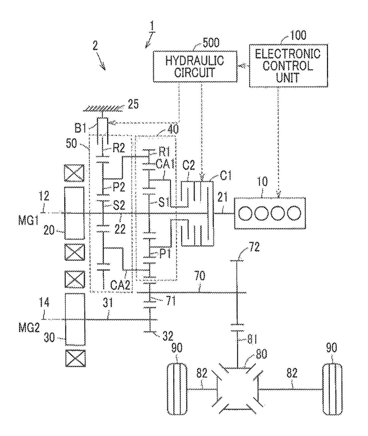
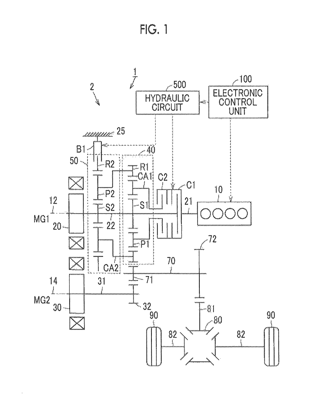
[0046]FIG. 1 is a view schematically showing an example of the general configuration of a vehicle 1 according to the present embodiment of the disclosure. The vehicle 1 includes a drive device 2, driving wheels 90, an electronic control unit 100 and a hydraulic circuit 500. The drive device 2 includes an engine 10, a first motor-generator (a first MG) 20, a second motor-generator (a second MG) 30, a first planetary gear device (a motive power division device) 40, a second planetary gear device 50, a clutch C1, a clutch C2 and a brake B1. The second planetary gear device 50, the clutches C1 and C2, the brake B1 and the hydraulic circuit 500 function as a changeover device. As will be described later, the changeover device changes...


PUM


Abstract

An electronic control unit is configured to select one of a series mode, a series-parallel mode and a parallel mode as a running mode. A load level of a hybrid vehicle is set to a value that is high in the order of a load level at which the parallel mode is selected, a load level at which the series-parallel mode is selected, and a load level at which the series mode is selected. That is, the electronic control unit selects the series-parallel mode in an intermediate load region, selects the series mode in a low load region, and selects the parallel mode in a high load region.

Description

INCORPORATION BY REFERENCE[0001]The disclosure of Japanese Patent Application No. 2016-128980 filed on Jun. 29, 2016 including the specification, drawings and abstract is incorporated herein by reference in its entirety.BACKGROUND1. Technical Field[0002]The disclosure relates to a control apparatus for a hybrid vehicle that is configured to select one of a series mode, a series-parallel mode and a parallel mode as a running mode, and a control method for the hybrid vehicle.2. Description of Related Art[0003]A hybrid vehicle is equipped with an engine and a motor as driving force sources. Conventionally, series running, series-parallel running and parallel running are known as methods in which the hybrid vehicle runs using both the motive power of the engine and the motive power of the motor. These three running methods are different in motive power transmission path of the engine from one another.[0004]Series running is a method in which the engine is connected to a generator, the m...

Claims


Application Information

Patent Timeline
Patent Type & Authority Patents(United States)
IPC IPC(8): B60W10/02B60W20/10B60W10/06B60W10/08B60W10/26B60L15/20B60L11/12B60K6/543B60K6/442B60L50/15B60L50/16
CPCB60K6/442B60K6/543B60L11/123B60L15/2045B60W20/10B60W10/06B60W10/08B60W10/26B60W10/02B60K6/445B60W30/1882B60W20/20Y02T10/56Y02T10/6286Y02T10/6239Y02T10/7258Y02T10/84B60W2520/10B60W2540/10B60W2710/0644B60W2710/1038B60L50/61Y02T10/40Y02T10/62Y02T10/70Y02T10/72B60K6/24B60K6/26B60K6/365B60W20/00B60Y2200/92
Inventor OBA, HIDEHIRO
Owner TOYOTA JIDOSHA KK
Why Eureka
Try Eureka