Heat dissipating device combined structure

a combined structure and heat dissipation device technology, applied in the direction of printed circuit aspects, basic electric elements, electrical apparatus construction details, etc., can solve the problems of affecting processing efficiency and service life, and increasing manufacturing costs, so as to reduce manufacturing costs, reduce manufacturing costs, and facilitate disassembly and assembly.

Active Publication Date: 2018-06-05
CHIN MEI CHIN CO LTD
View PDF3 Cites 7 Cited by
  • Summary
  • Abstract
  • Description
  • Claims
  • Application Information

AI Technical Summary

Benefits of technology

[0006]Accordingly, in order to resolve the aforementioned problems, the primary object of the present invention lies in providing a heat dissipating device combined structure that is convenient to disassemble and assemble, able to achieve a stable fastening, and reduces the manufacturing cost.
[0007]In order to attain the aforementioned object, the present invention provides a heat dissipating device combined structure, comprising: a heat sink and a clasp member, wherein the heat sink is provided with a bottom portion. A plurality of heat dissipating fins extend from the surface of the bottom portion, and at least one expanded portion extends from sides thereof. The clasp member is provided with a base, and areas on two sides of the base are respectively perpendicularly extended with a side, and a conduit is formed between the two sides. The aforementioned heat sink and a circuit board are disposed inside the conduit, and at least one ledge portion is formed on the sides and extend toward the direction of the conduit. Moreover, a plurality of air foils extend from another end position of the sides relative to the base. A slanting portion is provided on each of the air foils, and each of the end edges of the slanting portions clasp the corresponding expanded portion, thereby enabling the circuit board to be correspondingly disposed between the bottom portion and the base. Furthermore, the bottom surface of the circuit board is correspondingly mounted on the ledge portions, thereby enabling at least one exothermic electronic component on the top surface of the circuit board to be attached the bottom portion of the heat sink, as well fixing the circuit board between the slanting portions and the ledge portions. Accordingly, when the aforementioned heat sink and the circuit board are disposed inside the aforementioned conduit, the circuit board is mounted on the ledge portions, the electronic components on the upper side of the circuit board are attached to the bottom portion of the aforementioned heat sink, and the expanded portions of the heat sink are clasped by the slanting portions, further achieving the effectiveness of convenient disassembling and assembling, stable fastening, and reducing manufacturing cost.

Problems solved by technology

However, excessive heat energy from the electronic components affects the processing efficiency and serviceable life thereof.
However, because the heat dissipating device cannot be directly fixedly disposed to the electronic components, thus, the electronic information industry uses a clasp member to fix the heat sink to the circuit board.
However, disassembling and assembling the clasp member are considerably inconvenient, moreover, the manufacturing cost is also correspondingly increased.

Method used


Image

  • Heat dissipating device combined structure
  • Heat dissipating device combined structure
  • Heat dissipating device combined structure

Examples


Embodiment Construction

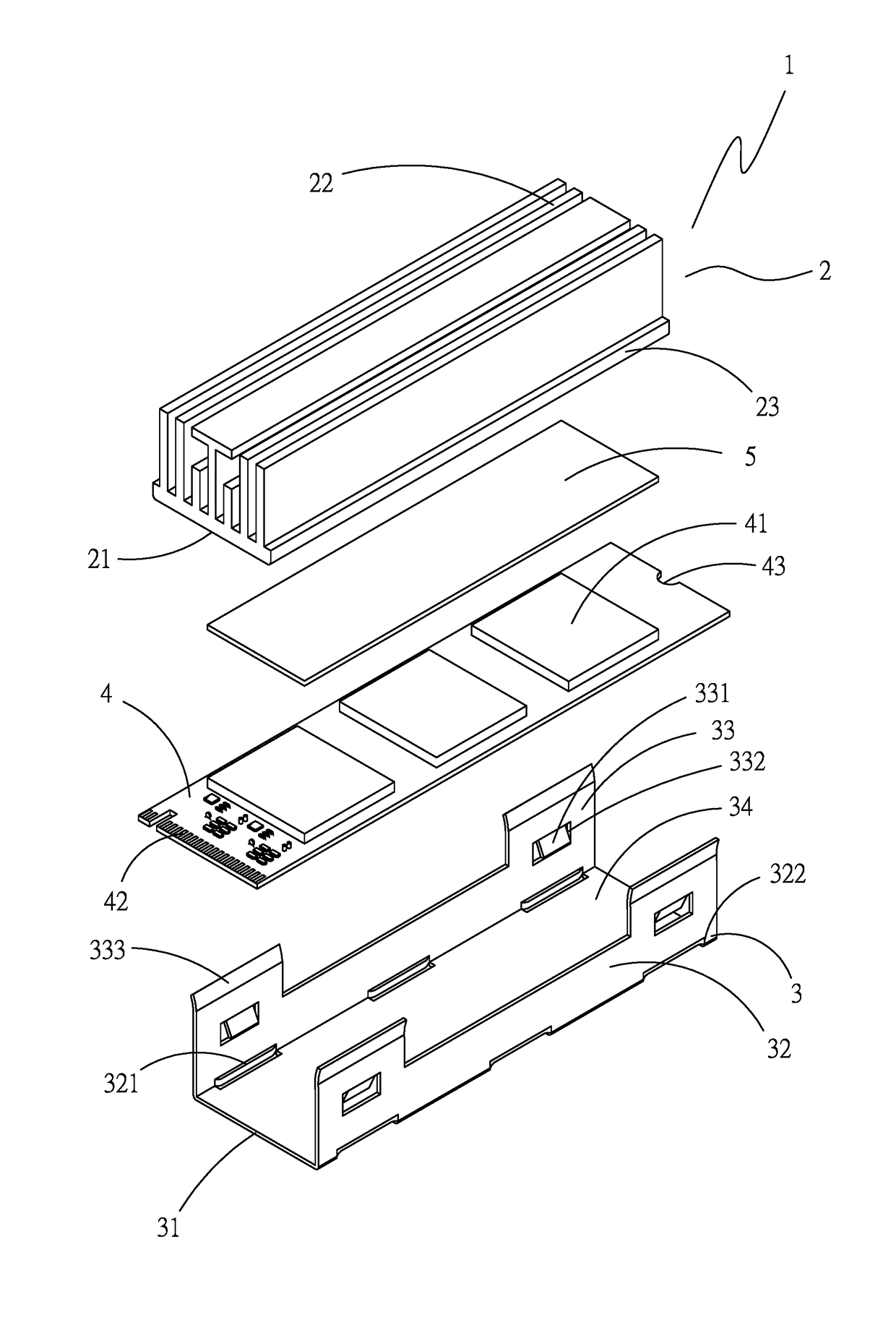
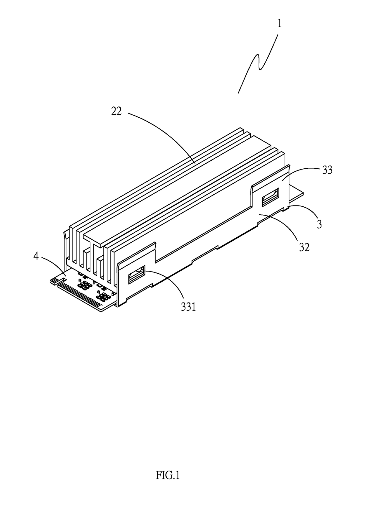
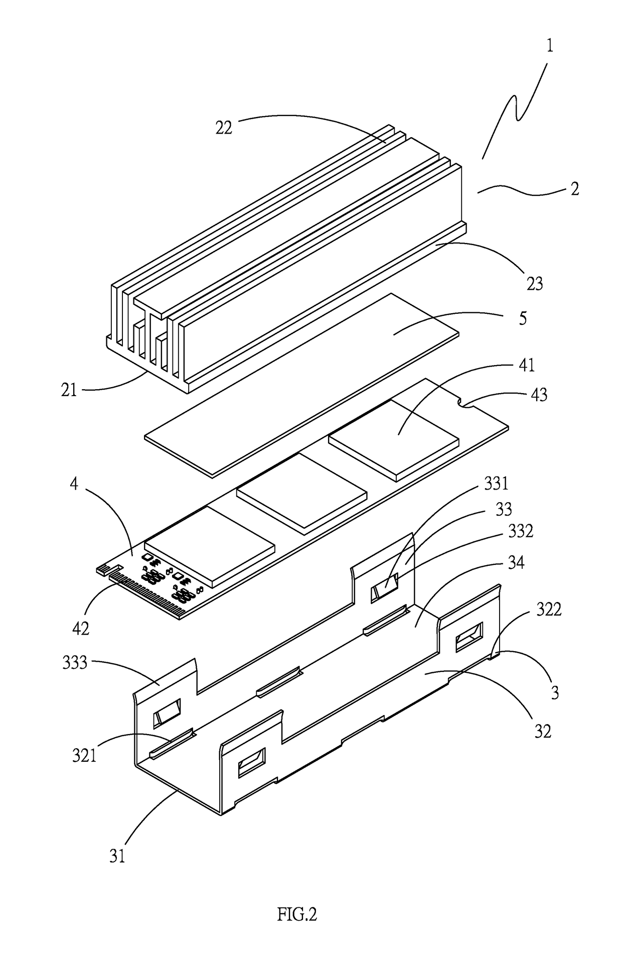
[0018]Referring to FIGS. 1 to 3, which show an assembled elevational schematic view, an exploded elevational schematic view, and an assembled cutaway schematic view of a preferred embodiment of the present invention, respectively, and it can be clearly seen from the drawings that a heat dissipating device combined structure 1 comprises a heat sink 2 and a clasp member 3. The heat sink 2 is provided with a bottom portion 21 and a plurality of heat dissipating fins 22, moreover, at least one expanded portion 23 horizontally, outwardly extends from the two sides of the bottom portion 21, and the clasp member 3 is provided with a base 31. Areas on two sides of the base 31 are respectively perpendicularly extended with a side 32, and a conduit 34 is formed between the two sides 32. At least one ledge portion 321 and a side groove 322 are formed on each of the sides 32. The ledge portions 321 respectively integrally extend from the sides of the side grooves 322 and extend toward the direc...


PUM


Abstract

The present invention provides a heat dissipating device combined structure, which consists of a heat sink and a clasp member. At least one expanded portion extends from the heat sink, and a side extends from each of the two sides of a base of the clasp member to form a conduit. The heat sink and a circuit board are disposed inside the conduit, and at least one ledge portion is formed on the sides. Moreover, a slanting portion extends from and is provided on air foils configured on the sides, and the ends of the slanting portions respectively clasp the expanded portions. Accordingly, the circuit board is mounted on the ledge portions, and electronic components on the circuit board are attached to the bottom portion of the aforementioned heat sink.

Description

BACKGROUND OF THE INVENTION[0001](a) Field of the Invention[0002]The present invention relates to a heat dissipating device, and more particularly to a heat dissipating device combined structure that is convenient to disassemble and assemble, able to achieve a stable fastening, and reduces the manufacturing cost.[0003](b) Description of the Prior Art[0004]Along with the rapid development in the electronic information industry, the processing capacity of electronic components, such as the central processing unit, continuously increases. However, excessive heat energy from the electronic components affects the processing efficiency and serviceable life thereof. Hence, heat conduction components used to effect heat absorption and heat dissipation for the electronic components are generally heat dissipating devices such as a heat sink or a heat conducting plate. However, because the heat dissipating device cannot be directly fixedly disposed to the electronic components, thus, the elect...

Claims


Application Information

Patent Timeline
Patent Type & Authority Patents(United States)
IPC IPC(8): H01L23/40H05K1/02H05K7/20
CPCH05K7/20409H05K1/0203H05K2201/066H05K2201/10393H01L23/367H01L23/4093H01L2023/4068
Inventor WANG, CHUN-CHIEH
Owner CHIN MEI CHIN CO LTD
Why Eureka
Try Eureka