Power converting apparatus

a power conversion and power technology, applied in mechanical equipment, machines/engines, gearing, etc., can solve the problems of power no longer being transmitted, mechanical damage or fatigue, and conversion efficiency may remarkably decrease, so as to achieve efficient transmission and considerable increase in generation efficiency

Active Publication Date: 2018-06-12
INGINE
View PDF46 Cites 9 Cited by
  • Summary
  • Abstract
  • Description
  • Claims
  • Application Information

AI Technical Summary

Benefits of technology

[0009]According to an embodiment of the present invention, a generation efficiency may considerably increase by receiving a power from a power source, producing electricity by rotating an output shaft connected to a generator using a portion of the received power, accumulating a remaining portion of the received power in an energy storage device, and rotating the output shaft using the accumulated energy when a power is not transmitted from a buoyant body, the power source that performs irregular motions within a predetermined range like the buoyant body floating in the ocean, and generates an intermittent linear power.
[0010]In particular, a power converting apparatus according to an embodiment of the present invention may connect a plurality of tensile force transmitting members to the buoyant body corresponding to the power source at predetermined angles, and efficiently transmit, to an input shaft, both a linear power occurring in a vertical direction and a linear power occurring in a horizontal direction by waves. Thus, a rotation power may be transmitted continuously to the output shaft to produce electricity.

Problems solved by technology

Thus, in a case in which a linear motion of the buoyant body occurs in a horizontal direction by waves, the power converting apparatuses may not convert the linear power into a rotation power, or a conversion efficiency may remarkably decrease and mechanical damage or fatigue may occur.
In such a method, when a length of the rope runs out, a power may no longer be transmitted.
Thus, a continuity of the power transmission may be lost, and a generation efficiency may decrease.

Method used


Image

  • Power converting apparatus
  • Power converting apparatus
  • Power converting apparatus

Examples


Embodiment Construction

[0016]Hereinafter, preferred embodiments of a power converting apparatus according to the present invention will be described in detail with reference to the accompanying drawings.

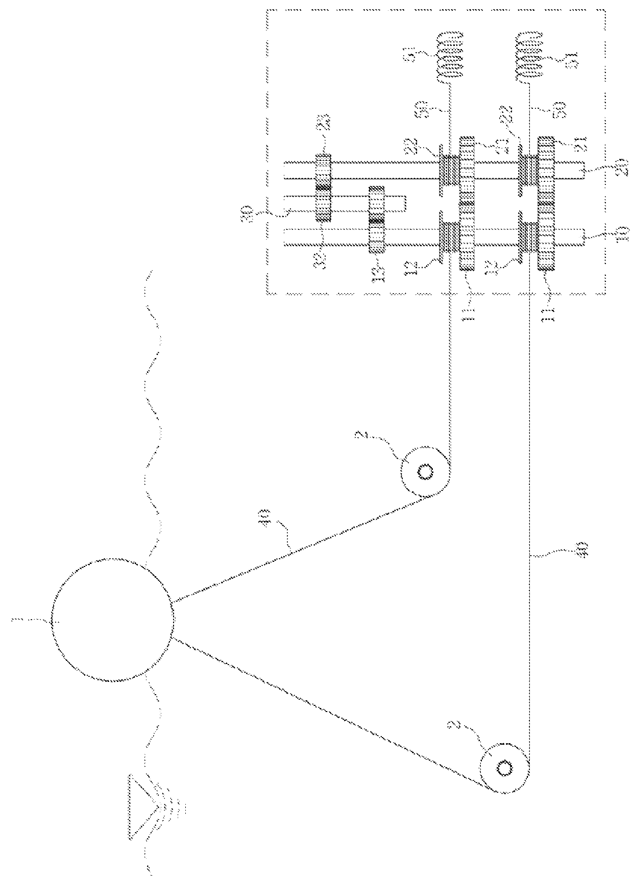
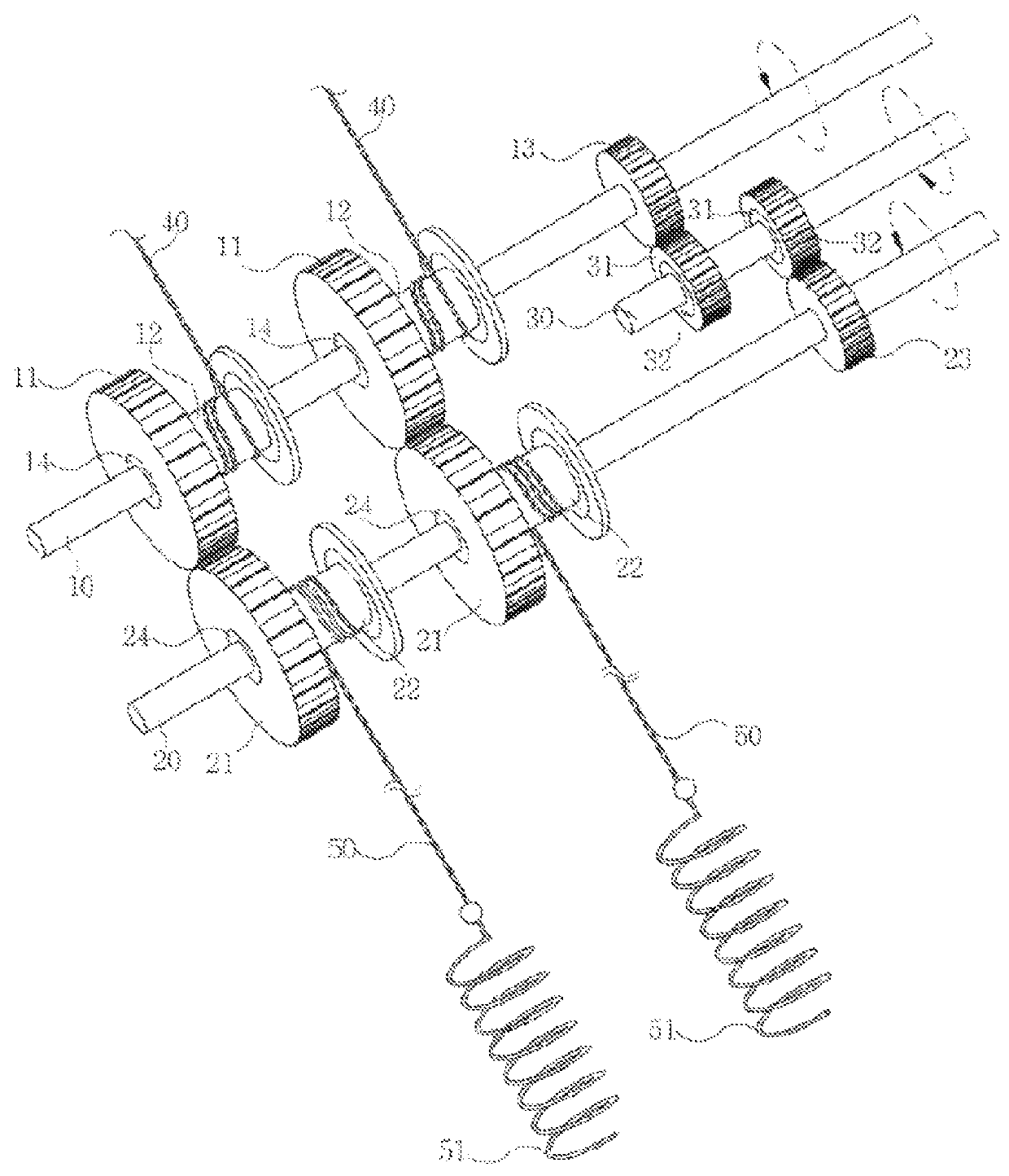
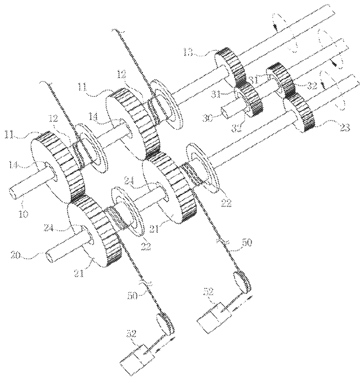
[0017]Referring to FIGS. 1 and 2, a power converting apparatus according to an embodiment of the present invention includes a first tensile force transmitting member 40 configured to be connected to a buoyant body 1 that floats and performs a motion in the ocean and transmits a tensile force; an input shaft 10 configured to be connected to the first tensile force transmitting member 40 and perform a rotary motion by a tensile force transmitted by the first tensile force transmitting member 40; a first power transmitting member 11 configured to be coupled to the input shaft 10 through a unidirectional rotation member 14 that allows only a unidirectional rotation and rotate along with the input shaft 10 or rotate while idling with respect to the input shaft 10; an energy transmitting shaft 20 configured to b...


PUM


Abstract

A power converting apparatus that may increase a generation efficiency by receiving a power from a power source, producing electricity by rotating an output shaft connected to a generator using a portion of the received power, accumulating a remaining portion of the received power in an energy storage device, and rotating the output shaft using the accumulated energy when a power is not transmitted from the power source, the power source that floats in the ocean, performs irregular motions in vertical and horizontal directions by waves within a predetermined range, and generates an intermittent linear power, is provided.

Description

TECHNICAL FIELD[0001]Embodiments of the present invention relate to a power converting apparatus, and more particularly, to a power converting apparatus that may increase a generation efficiency by receiving a power from a power source, producing electricity by rotating an output shaft connected to a generator using a portion of the received power, accumulating a remaining portion of the received power in an energy storage device, and rotating the output shaft using the accumulated energy when a power is not transmitted from the power source, the power source that floats in the ocean, performs irregular motions by waves within a predetermined range, and generates an intermittent linear power.BACKGROUND ART[0002]A wave power generation apparatus refers to facilities that rotate a generator using a flux of waves, and produce electric energy through a rotary motion of the generator. To solve an issue of constructing a large-scale power plant in the ocean in view of an output fluctuatio...

Claims


Application Information

Patent Timeline
Patent Type & Authority Patents(United States)
IPC IPC(8): F03B13/18F16H33/00F16H19/06F16H33/02F16D43/208F03B13/22F16H31/00
CPCF03B13/1885F16D43/208F16H19/0622F16H33/00F16H33/02F03B13/1895Y10T74/18152F05B2240/95F05B2240/97F05B2260/4031F05B2260/42F16H31/001Y02E10/38F03B13/22Y02E10/30F16H19/06F03B13/18
Inventor SUNG, YONGJUNKIM, JUNGHEELEE, DONGGEON
Owner INGINE
Why Eureka
Try Eureka