Supercharge Your Innovation With Domain-Expert AI Agents!

Radio frequency identification enabled mirrors

a technology of radio frequency identification and mirrors, applied in the field of wireless devices, can solve the problems of obstructing the driver's line of sight, affecting the aesthetics of the vehicle, and placing conventional rfid transponders that are obtrusive,

Active Publication Date: 2018-06-12
NEOLOGY INC
View PDF10 Cites 0 Cited by
  • Summary
  • Abstract
  • Description
  • Claims
  • Application Information

AI Technical Summary

Benefits of technology

The RFID-enabled mirror integrates RFID functionality into a vehicle's mirror, providing unobstructed visibility and aesthetic appeal while enabling communication with various frequency bands, such as UHF and HF, for toll systems and parking garages, and can provide notifications and control operational states.

Problems solved by technology

The placement of conventional RFID transponders tends to be obtrusive.
As such, the RFID transponder can obstruct the driver's line-of-sight and interfere with the aesthetic of the vehicle.

Method used


Image

  • Radio frequency identification enabled mirrors
  • Radio frequency identification enabled mirrors
  • Radio frequency identification enabled mirrors

Examples


Embodiment Construction

[0017]While certain embodiments are described, these embodiments are presented by way of example only, and are not intended to limit the scope of protection. The methods and systems described herein may be embodied in a variety of other forms. Furthermore, various omissions, substitutions, and changes in the form of the example methods and systems described herein may be made without departing from the scope of protection.

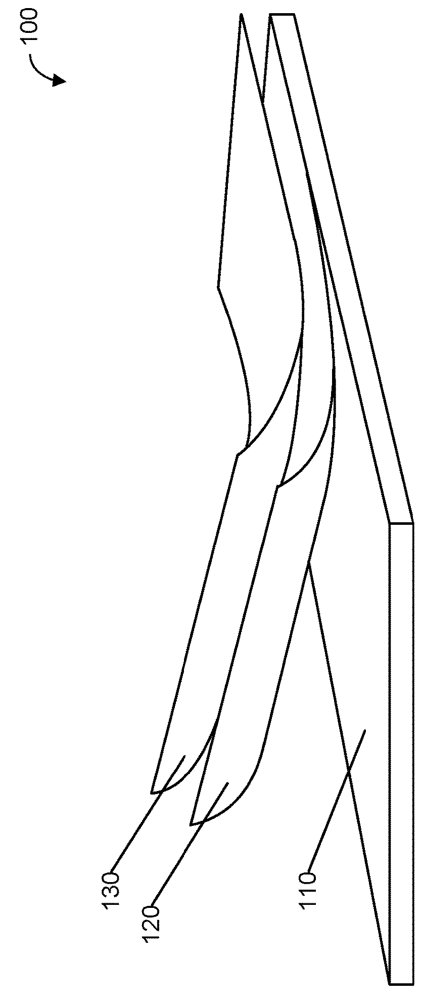
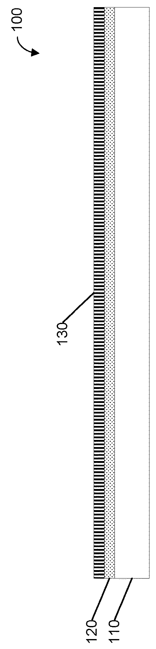
[0018]FIG. 1A illustrates a mirror 100 according to various embodiments. FIG. 1B illustrates a lateral cross-sectional view of the mirror 100 according to various embodiments. Referring to FIGS. 1A-B, the mirror 100 includes a substrate layer 110. In various embodiments, the substrate 100 can be any suitable transparent or substantially transparent material including, for example, but not limited to, glass, acrylic (i.e., polymethyl methacrylate (PMMA)), and polycarbonate (PC).

[0019]The mirror 100 further includes a reflective layer 120 that is deposited on top of ...


PUM


Abstract

A radio frequency identification (RFID) enabled mirror includes a mirror comprising a reflective layer. The reflective layer comprises at least one layer of a metallic material. At least one portion of the reflective layer is removed to form a booster antenna from a remaining portion of the reflective layer. A dielectric coating is applied to the mirror where the reflective layer was removed. The RFID-enabled mirror further includes an RFID chip coupled to the booster antenna.

Description

RELATED APPLICATIONS[0001]This patent application is a continuation of U.S. patent application Ser. No. 14 / 927,426 entitled “RADIO FREQUENCY IDENTIFICATION ENABLED MIRRORS” and filed on Oct. 29, 2015, which claims the benefit under 35 U.S.C. § 119(e) to U.S. Provisional Patent Application No. 62 / 072,416, entitled “RADIO FREQUENCY IDENTIFICATION ENABLED MIRRORS” filed on Oct. 29, 2014, the disclosures of which are incorporated herein by reference in their entirety as a part of this document.BACKGROUND1. Technical Field[0002]The various embodiments described herein are related to wireless devices, and more particularly to radio frequency identification (RFID) enabled mirrors.2. Related Art[0003]Radio frequency identification (RFID) technology plays a significant role in the regulation of motor vehicles and the provision of related services. For example, modern electronic toll systems (ETSs) and parking garages both rely heavily on RFID transponders. Thus, vehicles nowadays commonly ca...

Claims


Application Information

Patent Timeline
Patent Type & Authority Patents(United States)
IPC IPC(8): G06K19/077H01Q15/14H01Q1/22H01Q1/38H01Q13/10H01Q7/00H01Q5/378G02B5/08B60R1/12H01Q1/32
CPCG06K19/07794B60R1/12G02B5/0875H01Q1/2225H01Q1/3266H01Q1/38H01Q7/00H01Q13/106H01Q15/14H01Q5/378G02B5/085B60R2001/1261B60R2001/1276
Inventor NYALAMADUGU, SHESHIMULLIS, JOE
Owner NEOLOGY INC
Features
  • R&D
  • Intellectual Property
  • Life Sciences
  • Materials
  • Tech Scout
  • Unparalleled Data Quality
  • Higher Quality Content
  • 60% Fewer Hallucinations
Learn More