Soil gas and groundwater remediation system and method

a technology of soil gas and groundwater, applied in the field of soil and groundwater remediation, can solve the problems of significant environmental impact, cancer or other serious health impairment in people, and very common groundwater contamination

Active Publication Date: 2018-06-19
COUNCIL III EDWARD AUGUSTUS
View PDF26 Cites 4 Cited by
  • Summary
  • Abstract
  • Description
  • Claims
  • Application Information

AI Technical Summary

Problems solved by technology

Unfortunately, groundwater contamination is very common.
Man-made / anthropogenic sources are of particular concern as exposure to these types of contaminants can cause cancer or other serious health impairments in people.
VOCs are a class of chemical compounds that can often result in significant environmental impacts due to the ease the VOCs have migrating between soil and water.
The relative importance of these forces are difficult to differentiate and appear to strongly vary both temporally and under small scale site-specific conditions.
All of these prior known soil and groundwater remediation systems and methods require expensive engineered treatment wells and above ground infrastructure to support or control the remediation activities or the drilling of boreholes where expensive chemicals are injected or energy sources are used to treat the subsurface contamination.
The time needed to complete the soil and / or groundwater remediation often takes years to decades to complete, due to incorrect remedial designs, inefficiencies of the various treatment systems, and / or equipment failures.
Modifications to improve the efficiency of these treatment systems, after the systems are installed, are often difficult to identify and / or extremely expensive to implement.
Further, during the remediation period the impacted properties rarely can be used for any other purpose other than the operation of the treatment system.
The wells associated with prior known remediation systems are: 1) constructed to treat only the single zone adjacent to the screened well section; 2) not capable of allowing the area-wide mixing of atmospheric gases and temperatures into the vadose zone to enhance the remedial influence of barometric pumping; 3) not used as a single remedial treatment method to remove volatile and semi-volatile contaminants from impacted soil and groundwater; 4) not able to depress the volatilization potential of soil gas contaminants during colder weather; and 5) limited in location as the above ground components are restricted to areas where near ground obstructions are not a hazard to transportation systems, pedestrian or recreational uses.
The prior known remediation systems include various blowers, pumps and other components that are often expensive.
Power to run the mechanical and electrical components, as well as the ongoing equipment maintenance activities adds to the cost.
In addition, regulatory requirements in many states require that treatment wells and other components be removed after the systems are no longer in use, adding to the costs associated with operating these prior known remediation systems.

Method used


Image

  • Soil gas and groundwater remediation system and method
  • Soil gas and groundwater remediation system and method

Examples


Embodiment Construction

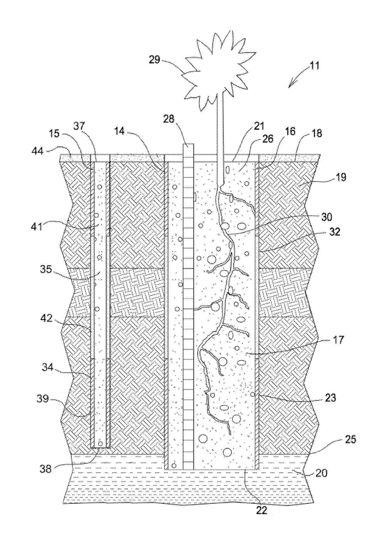
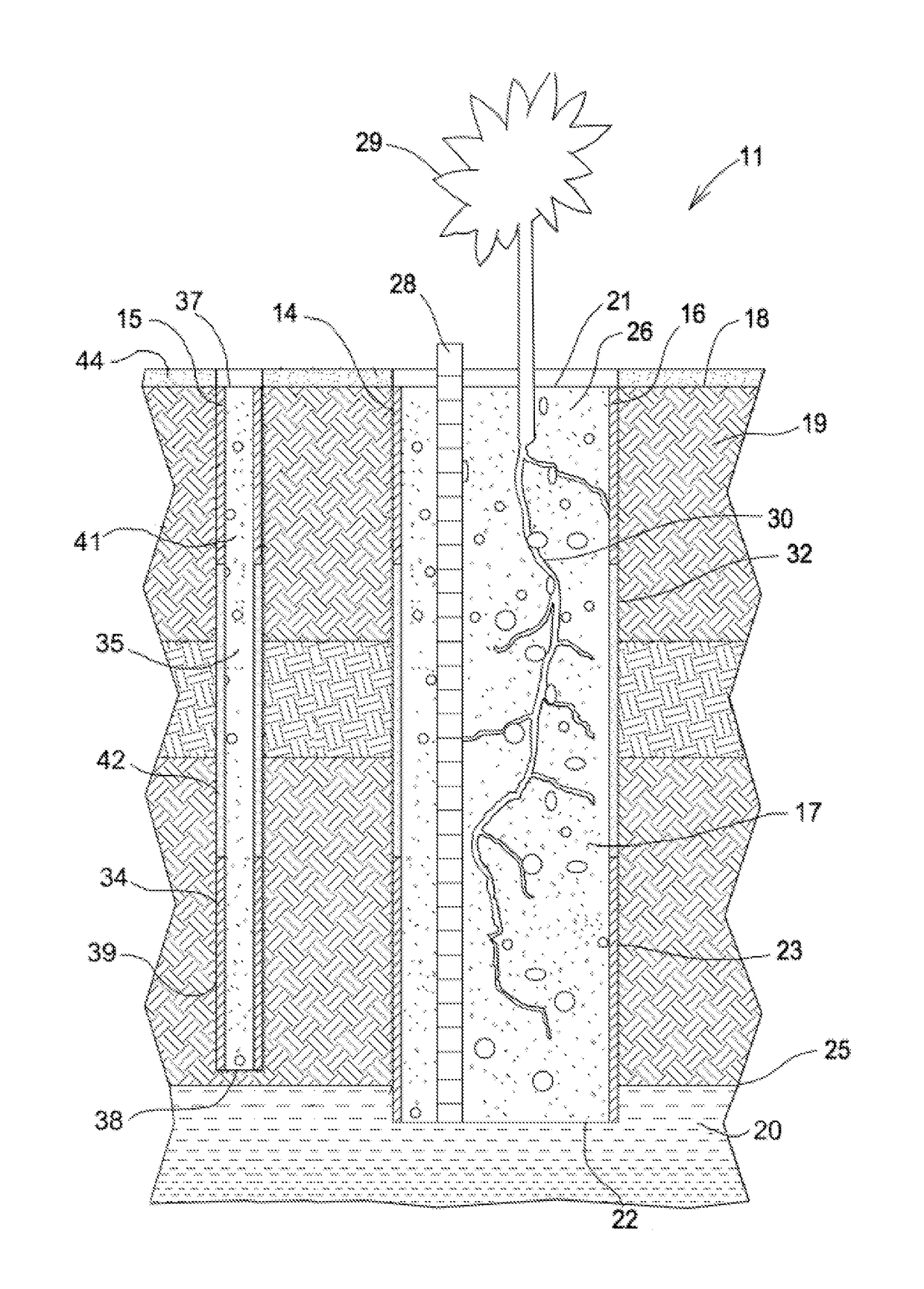
[0016]Referring to the FIGURE, a system 11 for intercepting, treating and venting vapors from contaminated soil and groundwater, embodying features of the present invention, a large borehole 14 and at least one spaced small borehole 15. The large borehole 14 has a liner 16 and fill material 17. The large borehole 14 has a selected diameter and is drilled from ground level 18 downwardly to a selected depth through the soil 19. The large borehole 14 has an open top end 21 at ground level 18, a spaced bottom end 22 at the selected depth, and an inwardly facing outer wall 23 of the soil 19 that extends from the top end 21 to the bottom end 22. The bottom end 22 can be located above, at or below the water table 25. The large borehole 14 defines a borehole cavity 26.

[0017]The liner 16 fits into the large borehole 14 against the outer wall 23, and extends around the borehole cavity 26 from the top end 21 to the bottom end 22. The liner 16 is gas permeable and can be made from organic or in...


PUM

PropertyMeasurementUnit
vapor pressuresaaaaaaaaaa
Henry's Law Constantaaaaaaaaaa
diameteraaaaaaaaaa

Abstract

A system for intercepting, treating and venting vapors from contaminated soil in the vadose zone and from contaminated groundwater includes a large borehole and at least one small borehole each having an open top end, a porous liner against the outer wall and porous fill material inside the liner. The fill material can include materials to retard and degrade contaminants in the vapors. The large and small boreholes can have impermeable sections in the liner, and impermeable ground cover around the top ends. The large borehole can also include a slotted aeration tube in the borehole and vegetation planted in the open end of the borehole. A method for intercepting, treating and venting of vapors from contaminated soil in the vadose zone and contaminated groundwater includes the system and pulling vapors out the top end of the large borehole with variations in atmospheric barometric pressure.

Description

TECHNICAL FIELD[0001]The present invention relates to soil and groundwater remediation, and more particularly to a passive system and method for intercepting, treating and venting volatile and semi-volatile contaminants from soil and groundwater.BACKGROUND ART[0002]Approximately half of the people in the United States rely on groundwater as their primary source of drinking water. Unfortunately, groundwater contamination is very common. Major sources of groundwater contamination include natural sources, underground storage tanks, septic tanks, hazardous waste sites, landfills, chemical storage facilities, chemical spills, and agricultural activities. Man-made / anthropogenic sources are of particular concern as exposure to these types of contaminants can cause cancer or other serious health impairments in people.[0003]The U.S. Environmental Protection Agency estimates that volatile organic chemicals (VOCs) are present in one-fifth of the nation's water supplies. VOCs are a class of che...

Claims


Application Information

Patent Timeline
Patent Type & Authority Patents(United States)
IPC IPC(8): B01D53/02B01D19/00C02F1/20B09C1/10B09C1/00
CPCB09C1/005B01D19/0036B09C1/105C02F1/20B09C1/002B09C2101/00
Inventor COUNCIL, III, EDWARD AUGUSTUS
Owner COUNCIL III EDWARD AUGUSTUS
Why Eureka
Try Eureka