Tubular heating-pipe solar water-heating-system with integral tank

a solar water heating and solar energy technology, applied in the safety of solar heat collectors, solar heat collectors, solar heat storage, etc., can solve the problems of reducing the efficiency of heat collection, slowing down the natural thermosyphon flow, and relatively stagnant hot water flow in the upper manifold, so as to improve the heat collection efficiency, and boost the heating capacity of the existing

Active Publication Date: 2009-08-04
TEOH SIANG TEIK
View PDF0 Cites 10 Cited by
  • Summary
  • Abstract
  • Description
  • Claims
  • Application Information

AI Technical Summary

Benefits of technology

[0018]In an alternative application of the invention the heating-pipes of the collector core extend into the bottom manifold of an existing solar water-heating-panel. Adding a collector core to an existing solar water-heating-panel boosts the heating capacity of the existing solar water-heating-system. The collector core also acts as a sediment trap which keeps the bottom manifold clean.
[0019]Because thermosyphon circulation is inherently weak and is susceptible to being slowed down by horizontal flows, or other impedances such as bends and elbows, eliminating such obstructions markedly improves heat collection efficiency. The advantage obtained by placing the outlet of the heating-pipes at the lower level of the hot-water storage-tank, pointing upwards as forms part of the present invention is not recognized in the Zinn patent where the hot-water inlet-pipes are at the very top of the hot-water storage-tank pointing downwards. The direct downward flow of cooler water from the lower level of the hot-water storage-tank through the cooler-water return-pipes to the lower end of the solar water-heating-panel also significantly improves collection efficiency.

Problems solved by technology

However, in solar water-heating-systems such as that disclosed in the Muramatsu '885 patent, the hot water must flow horizontally across the breadth of the solar water-heating-panel, or even worse, across two panels if it is a two panel system, before entering the hot-water storage-tank.
Moreover, before entering the hot-water storage-tank, the hot water must also flow through one or two elbow joints with all their attendant increase in resistance to flow due to form drag, i.e. eddying and turbulence, and friction drag etc. which impedes thermosyphon flow.
It is well known that slowing down natural thermosyphon flow reduces the efficiency of the heat collection because the water in the horizontal manifold becomes trapped, unable to move in its natural upwards direction.
This relatively stagnant flow of hot water in the upper manifold, in the upper part of the heating-pipes, and in the elbow joints becomes disadvantageously hot, and radiates away heat through glass covering the solar water-heating-panel.
Furthermore, some heat energy of the rising hot water in the vertical heating-pipes is also lost or expended in pushing the flow along the horizontal manifolds.
All of these losses reduce the overall heat transfer coefficient of efficiency.
Placing the inlet-pipes at the top of the hot-water storage-tank causes hot water to build-up in this area and to become congested once some hot water has accumulated at the top of the tank.
This congestion occurs because any new incoming hot water must drive the existing layer of hot water downwards within the hot-water storage-tank.
Again, thermal collection inefficiency rises as the amount of hot water increases.
Existing prior art solar hot water panels are also susceptible to mechanical damage if water in the heating-pipes freezes and cracks the heating-pipes.
This type of solar water-heating-system is inefficient since the water is only indirectly heated by the antifreeze solution.
Moreover, indirect solar water-heating panel systems are more expensive and complicated that a direct solar water-heating-system, and require maintenance including regular topping up of any intermediate-working liquid antifreeze solution if such is used.

Method used


Image

  • Tubular heating-pipe solar water-heating-system with integral tank
  • Tubular heating-pipe solar water-heating-system with integral tank
  • Tubular heating-pipe solar water-heating-system with integral tank

Examples


Embodiment Construction

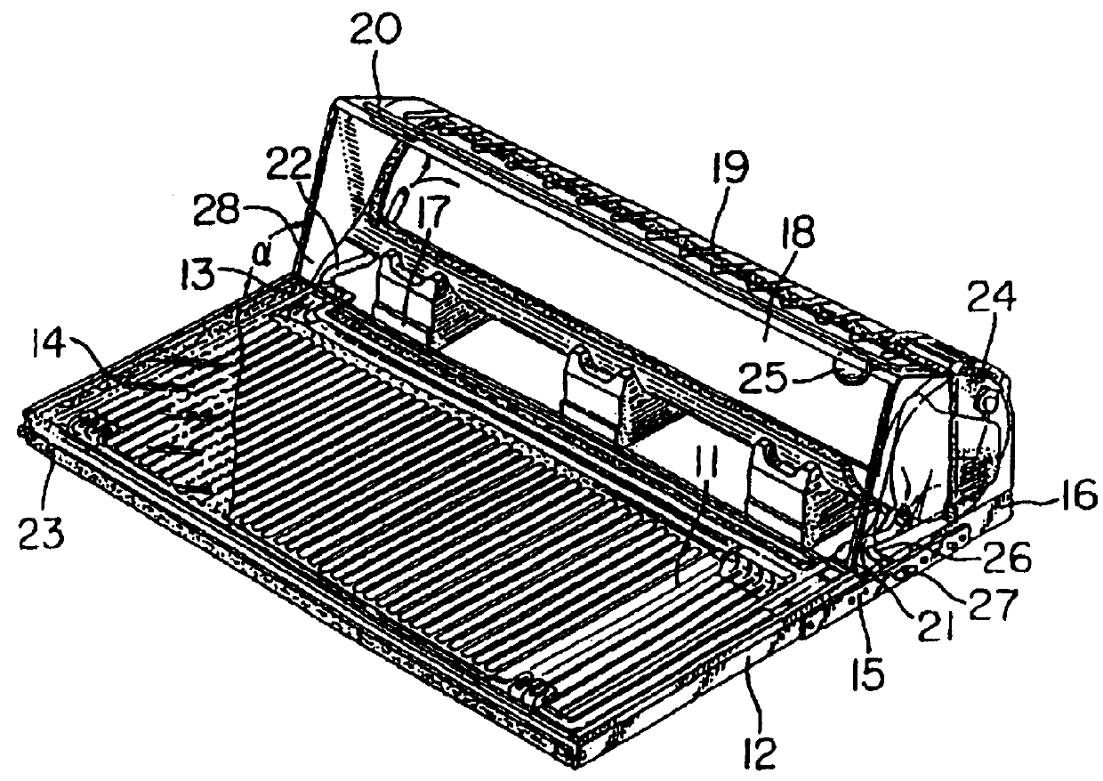
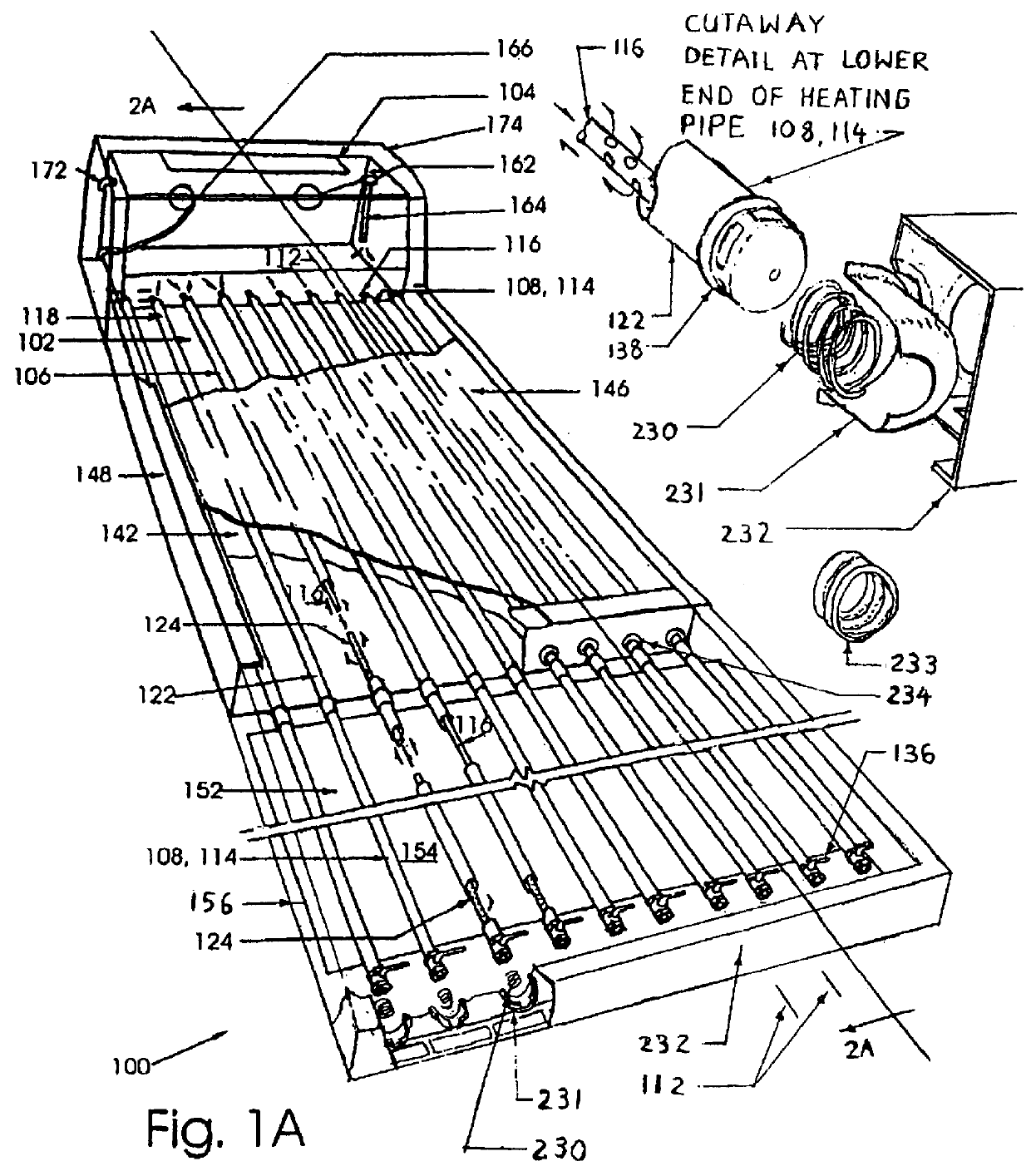
[0032]FIG. 1A depicts a solar water-heating-system in accordance with the present invention referred to by the general reference character 100. The solar water-heating-system 100 includes a solar water-heating-panel 102 directly connected to an insulated hot-water storage-tank 104. The solar water-heating-panel 102 includes a collector core 106 assembled from a plurality of heating-pipes 108. The heating-pipes 108 have longitudinal axes 112 that are arranged substantially parallel.

[0033]The heating-pipes 108 are free to move longitudinally to accommodate thermal expansion and contraction. The middle portions of the heating-pipes 108 are loosely secured by low friction sleeve collars 234 to the solar water-heating-panel casing 148 or frame 232 with the lower ends of the heating-pipes loosely secured or seated on a spring 230 or flexible corrugated polymer hose seat 233 in a cup 231 fixed onto the casing 148 or frame 232.

[0034]The heating-pipes 108 are preferably spaced equidistantly ...


PUM


Abstract

A collector core for a solar water-heating-system includes a plurality of heat-absorbing pipes each of which surrounds a cooler-water return-pipe. The heating-pipes may connect directly to an insulated hot-water storage-tank from which cooler water descends through the return-pipes into the heating-pipes. Upon reaching the end of the return-pipes, the cooler water flows outward into the space between the surrounding heating-pipes and the inner return-pipes. Upon warming, water between the two pipes rises upward back to the hot-water storage-tank thus completing the thermosyphon flow cycle. Preferably, the inner return-pipe is made of polyvinyl chloride ("PVC"), polybutelene ("PB"), or other compressible material which permits collector core operation both in freezing and non-freezing environments. Alternatively, the collector core may be added to an existing solar water-heating panel to improve its operation.

Description

[0001]This application is an application for a patent of addition in respect of Australian Patent No. 702793, the contents of which are incorporated herein by reference.TECHNICAL FIELD[0002]This invention relates generally to solar water-heating-systems, and more specifically to an improved solar water-heating-system having a collector core which includes heating-pipes in each of which countercurrent flows of hot and cold fluid pass in opposite directions.BACKGROUND ART[0003]In this specification, where a document, act or item of knowledge is referred to or discussed, this reference or discussion is not an admission that the document, act or item of knowledge or any combination thereof was at the priority date:[0004](i) part of common general knowledge; or[0005](ii) known to be relevant to an attempt to solve any problem with which this specification is concerned.[0006]A solar water-heating-system to which the present invention particularly relates comprises a solar water-heating-pa...

Claims


Application Information

Patent Timeline
Patent Type & Authority Patents(United States)
IPC IPC(8): F24J2/44
CPCF24S10/753F24S40/60F24S40/70F24S60/30F24S90/10Y02E10/44
Inventor TEOH, SIANG TEIK
Owner TEOH SIANG TEIK
Why Eureka
Try Eureka