Scroll type compressor having curved surface portions between the shaft and bearing means

Inactive Publication Date: 2000-03-07
MITSUBISHI ELECTRIC CORP
View PDF17 Cites 9 Cited by
  • Summary
  • Abstract
  • Description
  • Claims
  • Application Information

AI Technical Summary

Benefits of technology

In the scroll type compressor according to the present invention, a radial direction force is exerted on the orbiting scroll during a compression stroke, and the force is applied to the eccentric shaft portion which is provided on top of the crankshaft. As a result, the crankshaft is subject to flexture-deformation. In accordance with the present invention, the scroll type compressor is provided with such bearing means that the eccentric shaft portion, the main shaft portion or the sub shaft portion of the crankshaft has a curved surface, or has a central portion provided with a barrel shaped band portion to present a convex surfac

Problems solved by technology

This creates e.g. a problem in that load carrying capacities of the respective bearing parts can deteriorate to we

Method used


Image

  • Scroll type compressor having curved surface portions between the shaft and bearing means
  • Scroll type compressor having curved surface portions between the shaft and bearing means
  • Scroll type compressor having curved surface portions between the shaft and bearing means

Examples


Embodiment Construction

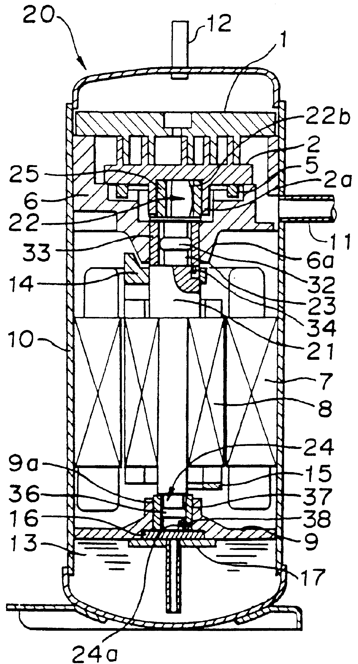
The scroll type compressor according to the present invention will be described in detail, referring to embodiments shown in the accompanying drawings. In FIG. 1, there is shown the scroll type compressor 20 according to a first embodiment of the present invention. In FIG. 1 showing the scroll type compressor 20 of the first embodiment, similar or corresponding parts are indicated by the same reference numerals as the conventional scroll type compressor shown in FIG. 17, and explanation of those parts will be omitted for the sake of simplicity.

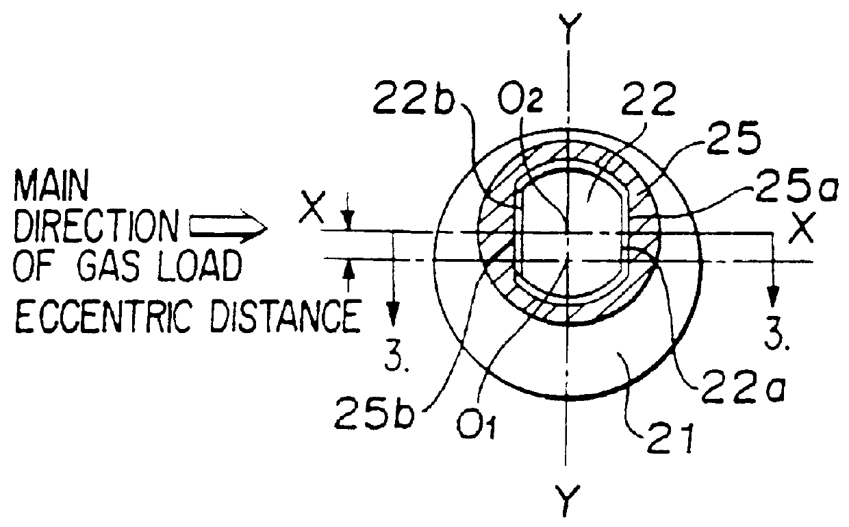
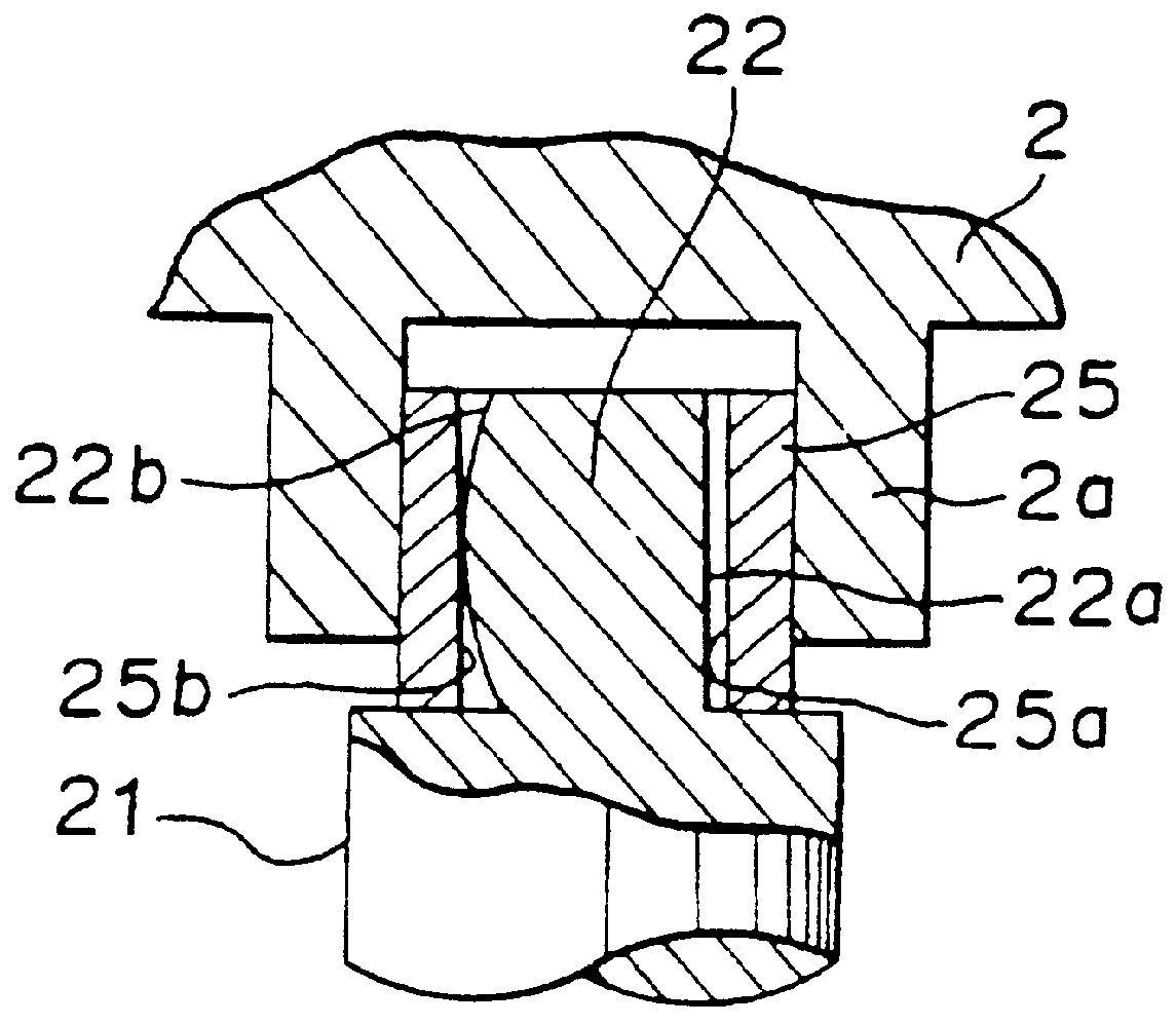
The scroll type compressor 20 of the embodiment includes a crankshaft 21 which has an electric motor rotor 8 fixed by shrinkage fit at an intermediate portion thereof in its axial direction. The crankshaft 21 has an upper portion formed integrally with an eccentric shaft portion 22 which is fitted into a bearing part 2a of an orbiting scroll 2 to give torque directly to the orbiting scroll 2. The crankshaft has a main shaft portion 23 formed t...


PUM


Abstract

A scroll type compressor comprising: a crankshaft having an eccentric shaft portion formed thereon; an orbiting scroll which is given torque by the crankshaft through the eccentric shaft portion; and bearing means for rotatably supporting the crankshaft; wherein at least one of the eccentric shaft portion and the bearing means is constituted by a rotatably engaged bushing and a curved surface portion.

Description

BACKGROUND OF THE INVENTIONThe present invention relates to a scroll type compressor, and more particularly to a scroll type compressor which is utilized in refrigeration and air conditioning systems.A conventional scroll type compressor, which has been disclosed in e.g. Japanese Unexamined Patent Publication No. 80088 / 1988, is constructed as shown in FIG. 17. In FIG. 17, reference numeral 1 designates a fixed scroll. Reference numeral 2 designates an orbiting scroll. Reference numeral 3 designates a crankshaft. Reference numeral 4 designates a driving bushing which is rotatably mounted in a bearing part 2a formed in the orbiting scroll 2. Reference numeral 5 designates an Oldham's ring. Reference numeral 6 designates a main frame. Reference numeral 6a designates a main bearing which is formed in the main frame 6. Reference numeral 7 designates an electric motor stator. Reference numeral 8 designates an electric motor rotor. Reference numeral 9 designates a sub frame. Reference nume...

Claims


Application Information

Patent Timeline
IPC IPC(8): F01C21/00F01C21/02F04C18/02F04C29/00F16D3/20F16D3/16F04C23/00
CPCF01C21/02F04C18/0215F04C29/0057F16D3/20F04C23/008Y10T403/32647F04C2240/807Y10T403/32622F04C2240/601F16C2360/42F04C18/02
Inventor SANO, FUMIAKIOIDE, MASAHIKONAKAMURA, TOSHIYUKIKOBAYASHI, NORIHIDEOGAWA, HIROSHISHIRAFUJI, YOSHINORIYAMAMOTO, TAKASHISAKAINO, KEIJU
Owner MITSUBISHI ELECTRIC CORP
Why Eureka
Try Eureka