Modularized assembly for bulk material analyzer

a technology of bulk material analyzer and module, which is applied in the direction of instruments, machines/engines, specific gravity measurement, etc., can solve the problem of difficult transportation of assembly, and achieve the effect of convenient handling

Inactive Publication Date: 2000-11-07
GAMMA METRICS
View PDF23 Cites 7 Cited by
  • Summary
  • Abstract
  • Description
  • Claims
  • Application Information

AI Technical Summary

Benefits of technology

By assembling the bulk material analyzer from such individual modules that easily can be handled separately, the bulk material analyzer assembly is more easily handled for transportation from one site to another, with the assembly easily being completed at a site where the bulk material analyzer is to be used.
Also, the bulk material analyzer of the present invention may readily be assembled about an in-place conveyor belt without having to sever the belt.

Problems solved by technology

The required quantity of radiation shielding material is such that the bulk material analyzer assembly is so large that the assembly is not easily handled for transportation from one site to another.

Method used


Image

  • Modularized assembly for bulk material analyzer
  • Modularized assembly for bulk material analyzer
  • Modularized assembly for bulk material analyzer

Examples


Embodiment Construction

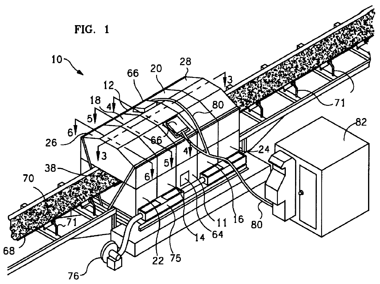
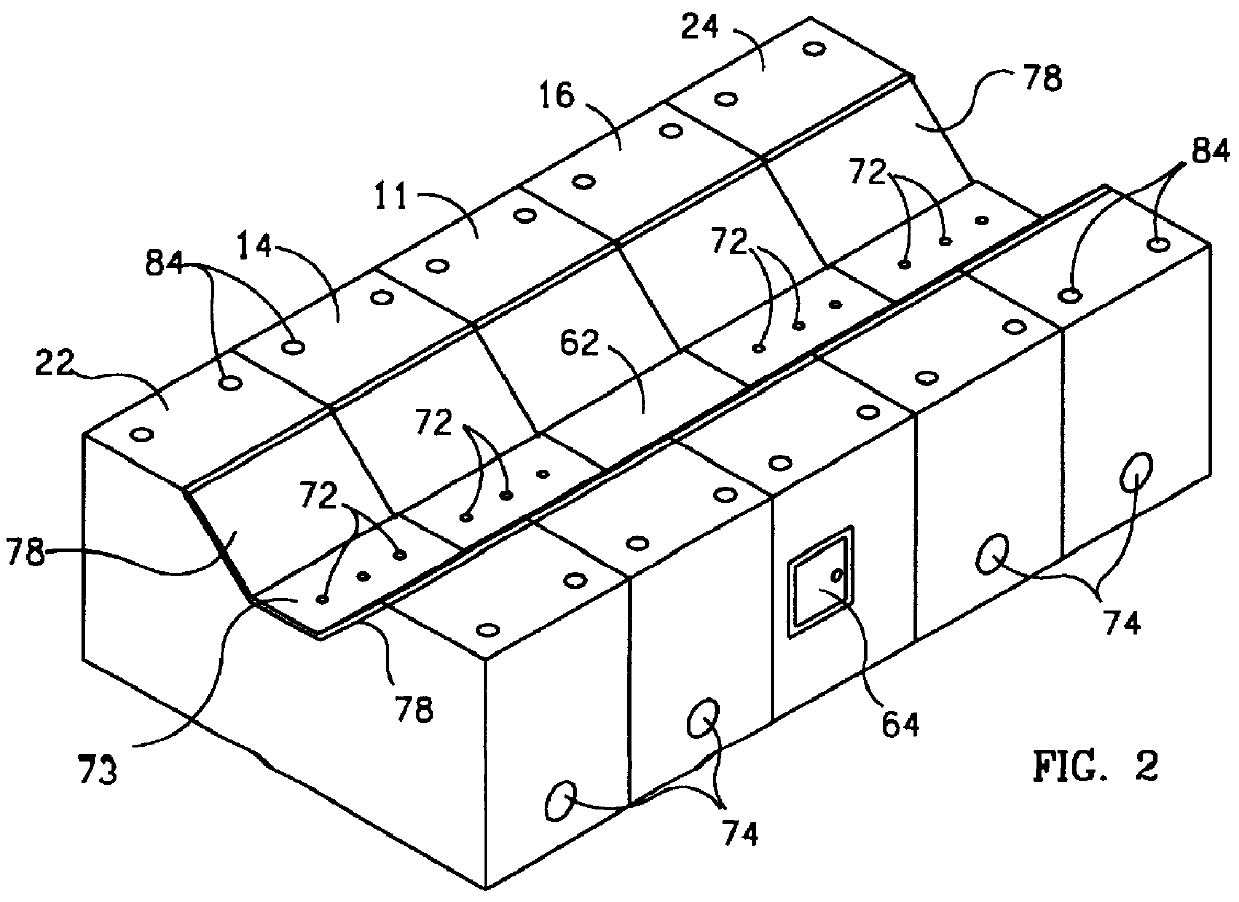
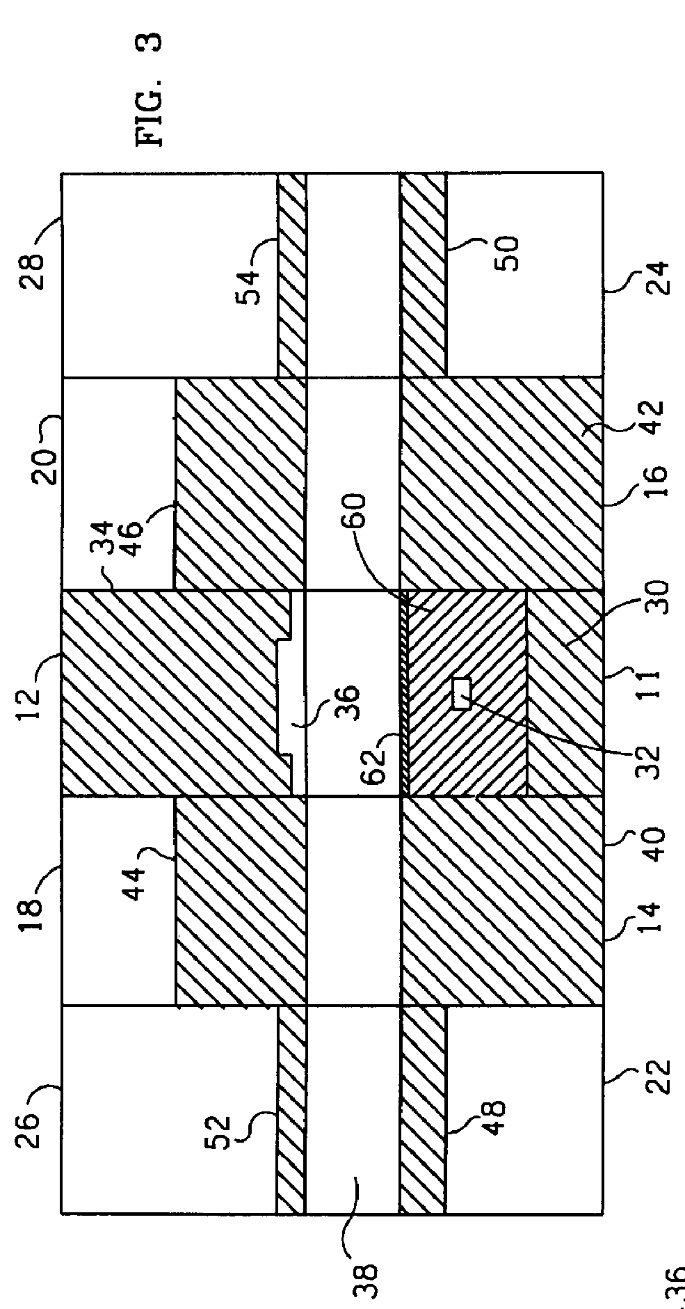
Referring to FIGS. 1 and 2, a preferred embodiment of the bulk material analyzer assembly 10 of the present invention includes a lower primary module 11, an upper primary module 12, a first lower secondary module 14, a second lower secondary module 16, a first upper secondary module 18, a second upper secondary module 20, a first lower tertiary module 22, a second lower tertiary module 24, a first upper tertiary module 26 and a second upper tertiary module 28.

The lower primary module 11 contains a first portion of radiation shielding material 30 and defines a pair of radiation source cavities 32 for receiving neutron sources 33, as shown in FIGS. 3 and 4. The upper primary module 12 contains a second portion of radiation shielding material 34 and defines a pair of radiation detector cavities 36 for receiving gamma-ray detectors 37, as also shown in FIGS. 3 and 4. The lower primary module 11 and the upper primary module 12 are so shaped that the upper primary module 12 can be placed ...


PUM

PropertyMeasurementUnit
shieldingaaaaaaaaaa
radiation shieldingaaaaaaaaaa
energy spectraaaaaaaaaaa

Abstract

A bulk material analyzer of the type in which the bulk material is transported through the material analyzer assembly on a conveyor belt between at least one radiation source and at least one radiation detector, includes a plurality of lower and upper modules that contain radiation shielding material and are so shaped as to define a passageway for the conveyor belt between the upper modules and the lower modules when the upper modules are placed on the lower modules. A primary centrally located lower module also includes the radiation sources and a primary centrally located upper module also includes the radiation detectors. Some of the outwardly located modules contain less radiation shielding material. The radiation shielding material includes a plurality of personally portable blocks. The conveyor belt is supported by compressed air passed through central upper wails in the outwardly located lower modules. The lower modules contain alignment members on upward facing surfaces thereof and the upper modules contain alignment members on downward facing surfaces thereof that are complementary to the alignment members on the upward facing surfaces in order to enable the upper modules to be accurately placed on the lower modules. The lower modules each include a central upper wall bounded by outwardly inclined inner side walls to define a trough for accommodating passage through the passageway of a conveyor belt having a contour corresponding to the trough. The container includes apertures disposed beneath at least part of the passageway, and includes conduits leading to the apertures from a port adapted to be connected to a source of compressed air so that the conveyor belt can be at least partially supported by compressed air while passing through the passageway.

Description

GROUND OF THE INVENTIONThe present invention generally pertains to bulk material analyzers and is particularly directed to an improved assembly for bulk material analyzers of the type in which the bulk material is transported through the material analyzer on a conveyor belt between at least one radiation source and at least one radiation detector.Bulk material analyzers are used to measure the elemental content of bulk materials. In one type of bulk material analyzer, the radiation source includes one or more neutron sources and the radiation detector includes one or more gamma-ray detectors that produce signals which are processed to provide a measurement of the elemental content of the bulk material. When the bulk material is bombarded by neutrons, secondary emissions of gamma-rays are produced from the bulk material. Different characteristic gamma-ray energy spectra are produced from different elements in the bulk material. By processing detected signals that are indicative of th...

Claims


Application Information

Patent Timeline
Patent Type & Authority Patents(United States)
IPC IPC(8): G01N23/22G01N23/222G01N9/24
CPCG01N23/222G01N9/24
Inventor ATWELL, THOMASISAACSON, CHRIS A.SMITH, ANDREW H.STRONSKI, JAMES P.ACKERMAN, RICHARD E.CONWELL, RICHARD L.SHYU, CHAUR-MING
Owner GAMMA METRICS
Why Eureka
Try Eureka