Enhanced tubular heat exchanger

a technology of heat exchanger and tube, which is applied in the direction of indirect heat exchangers, lighting and heating apparatus, heating types, etc., can solve the problems of inefficiency in the amount of heat transferred from heated flue gases to circulating air, and the flow in the center may only be minimal, so as to achieve efficient heat transfer, promote circulation air flow, and reduce manufacturing costs

Inactive Publication Date: 2001-01-09
CARRIER CORP
View PDF31 Cites 18 Cited by
  • Summary
  • Abstract
  • Description
  • Claims
  • Application Information

AI Technical Summary

Benefits of technology

One object of the present invention is to provide a heat exchanger element which more efficiently transfers heat from the heated flue gases to the circulation air.
Another object is to provide a heat exchanger element in which the laminar flow in the center of the conduit is more effectively disrupted and radially mixed.
A further object is to provide a heat exchanger element which is less expensive to manufacture.
A still further object is to provide a heat exchanger conduit for a furnace which promotes circulation air flow around the exterior of the conduit and minimizes the occurrence of hot spots.
Also an object of the present invention is to provide a heat exchanger conduit for a furnace which reduces the pressure drop across the heat exchanger conduits.

Problems solved by technology

Also, the conduits generally include two or more elongated sections connected by bend sections so that the interior flow of heated flue gas is disrupted and impacts interior surfaces of the tubes to promote further heat exchange.
However, a problem with prior art heat exchanger conduits involves the inefficiency in the amount of heat transferred from the heated flue gases to the circulating air.
A problem with this configuration is that although disruption is caused within the flow along the inner surfaces of the wall, the flow in the center may only be minimally effected.
A problem with this configuration is the expense involved in manufacturing tubes which vary in cross-sectional shape over their length.
The problem with the clam-shell configuration is that the flow produced by the circulator fan is only minimally disrupted in the spaces between the plates.
A problem with the tubular configuration is that the first row of cylindrical elongated portions causes a high pressure drop in the circulation flow resulting in the circulation flow only minimally wrapping around the other row or rows of elongated portions so that hot spots develop on the downstream elongated portions.

Method used


Image

  • Enhanced tubular heat exchanger
  • Enhanced tubular heat exchanger
  • Enhanced tubular heat exchanger

Examples


Embodiment Construction

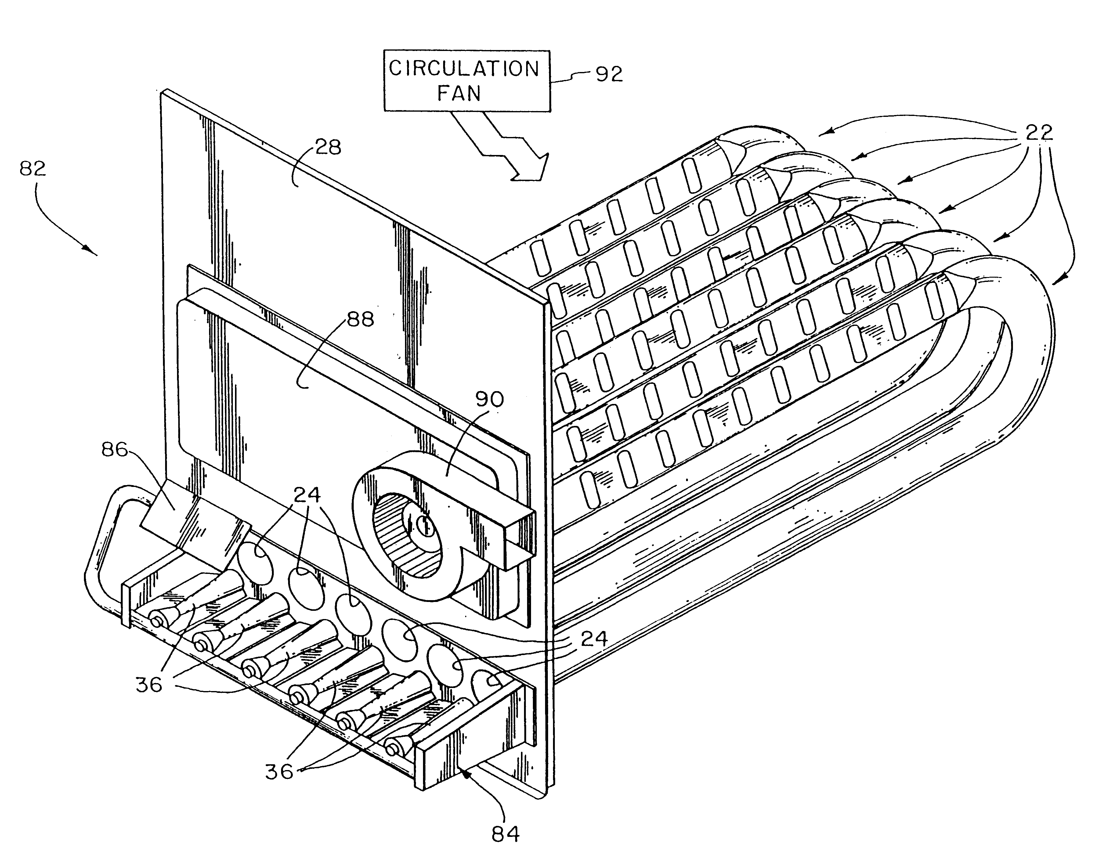
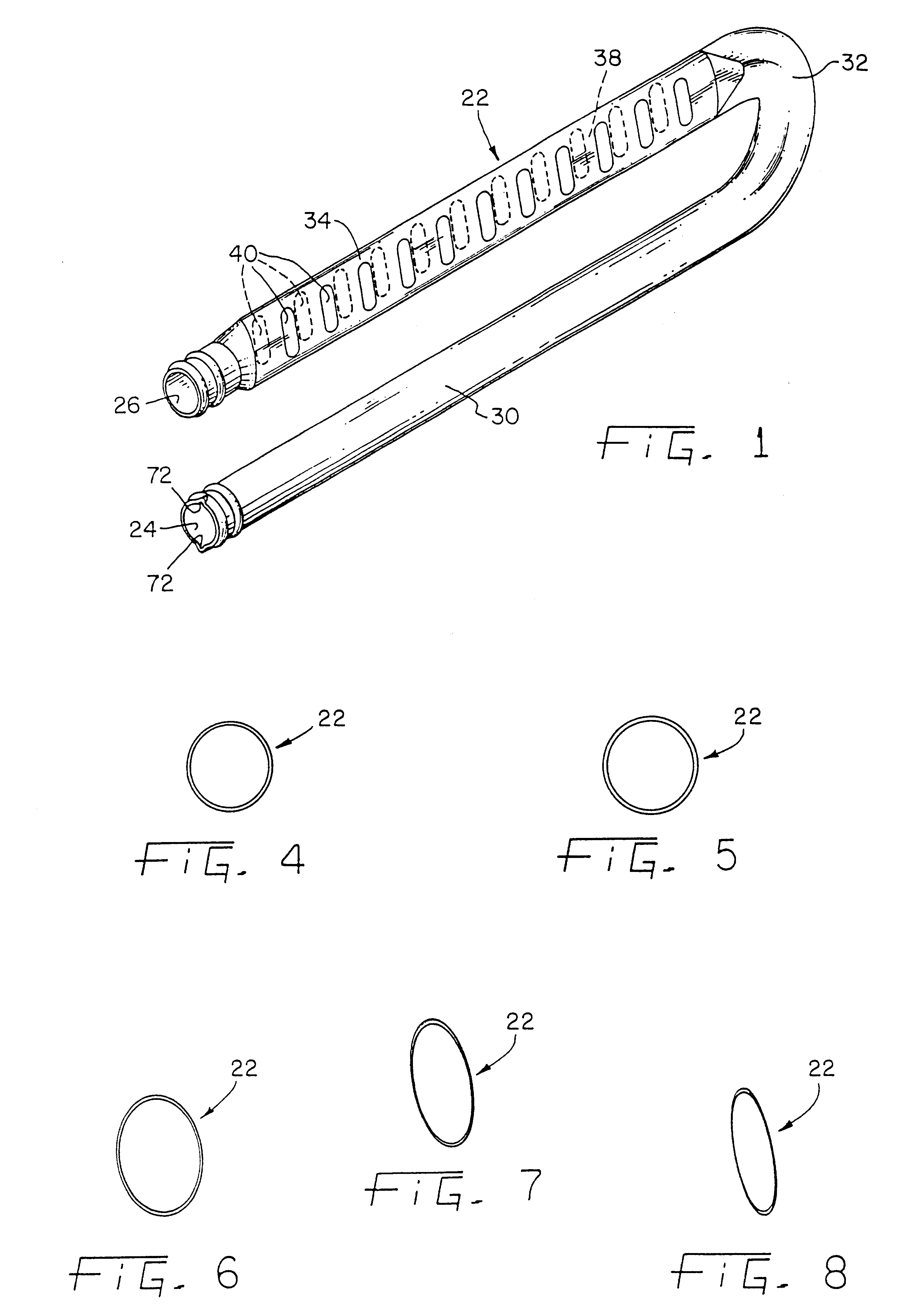
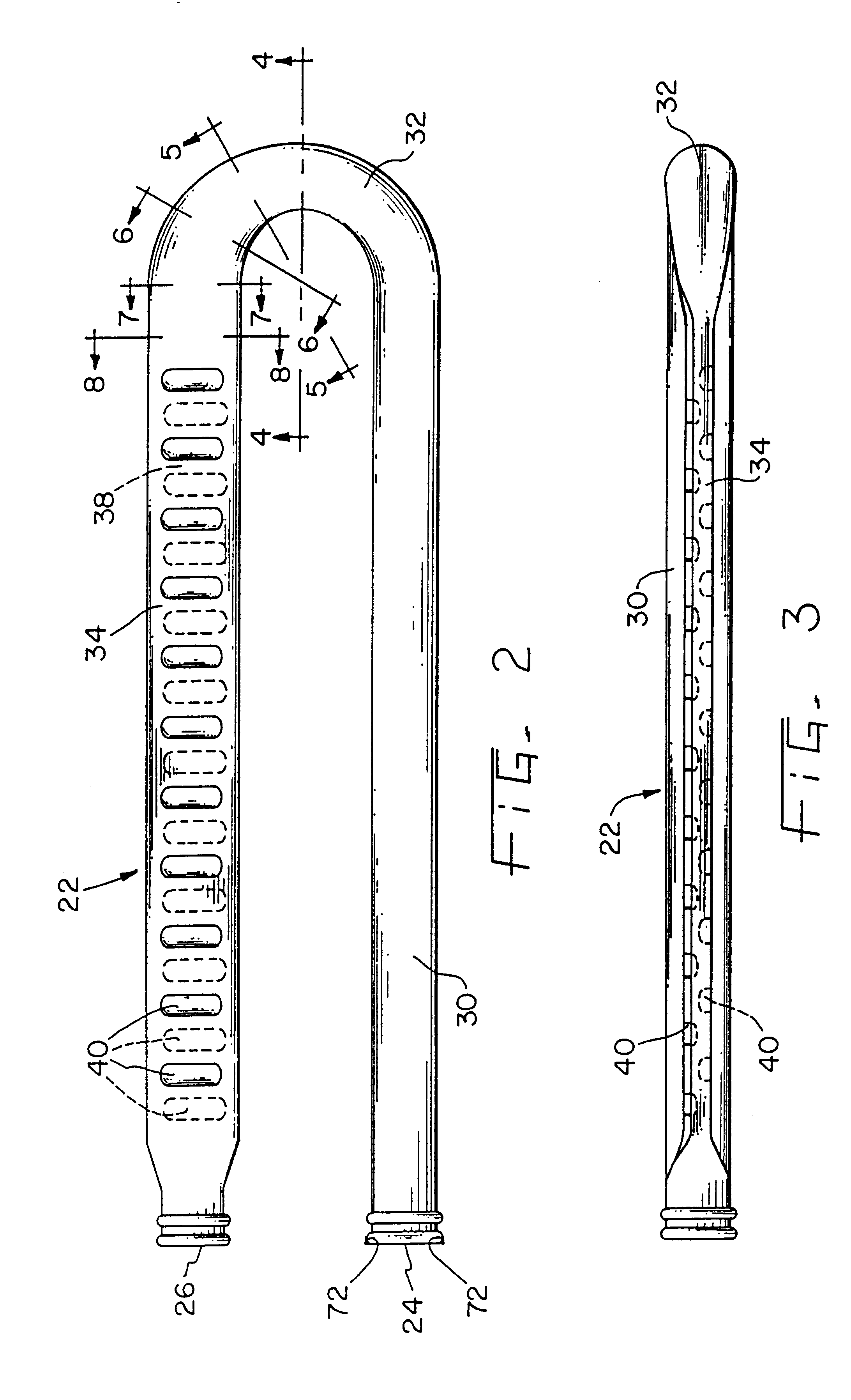
The present invention relates to an elongated heat exchanger tube 22 as depicted in FIG. 1. Tube 22 includes inlet 24 and outlet 26 for attaching to a heat exchanger panel 28 (see FIGS. 9 and 10). Connecting inlet 24 and outlet 26, tube 22 includes flue portion 30 which is adjacent to inlet 24, bend portion 32 which is adjacent to flue portion 30, and enhanced portion 34 which is disposed between bend portion 32 and outlet 26. Flue portion 30 is generally cylindrical in shape and receives the flame which is produced by operation of inshot burner 36 (see FIG. 9).

In accordance with the present invention, bend portion 32 decreases in cross-sectional area approaching enhanced portion 34, see FIGS. 2 and 4-8. Enhanced portion 34 is considerably narrower than flue portion 30, compare FIGS. 4 and 8 (although FIG. 4 shows a cross-section of bend portion 32, the depicted shape is representative of the general cross-sectional shape of flue portion 30). The narrowness of enhanced portion 34 pr...


PUM


Abstract

The present invention is an enhanced tubular heat exchanger for a furnace <INS-S DATE="20010109" ID="INS-S-00001">with the heat tubes of the heat exchanger having two straight sections connected by a bend<INS-E ID="INS-S-00001">. The tubes of the heat exchanger include an enhanced portion which has a smaller cross-sectional area than the flue portion, in the form of an elliptically shaped tube. The enhanced portion further includes turbulators to promote the heat exchange from the heated flue gases. Circulation of air around the exterior of the tubes is also facilitated because the enhanced portion is disposed at a small angle relative to the flue portion. A plurality of tubes are disposed within the heat exchanger so that the circulation air first flows over the enhanced portions then over and around the generally cylindrical portions. This lowers the initial pressure drop in the circulation air flow and thereby facilitates the circulation of and heat transfer to the air being heated.

Description

BACKGROUND OF THE INVENTION1. Field of the InventionThe present invention relates to heat exchangers for furnaces. More specifically, the field of the invention is that of heat exchanger tubes which provide passageways for heated flue gases within furnace heat exchangers.2. Prior ArtTubular conduits are used in heat exchangers to provide an interior conduit for flue gases and exterior heat transfer surface for circulating air. The interior conduits may be formed from metallic clam-shell plates wherein two clam-shell plate surfaces are connected together to form the conduits, or the tubular conduits may comprise metal tubes. Within furnaces, such tubular conduits provide a passageway for flue gases, the heated products of combustion, which flow through the heat exchanger. The flue gas flow transfers heat to the material defining the passageway which then transfers the heat to air circulating over and around the heat exchanger.The heat exchanger contains the flue gas flow. An inducer ...

Claims


Application Information

Patent Timeline
Patent Type & Authority Patents(United States)
IPC IPC(8): F28F13/00F28F13/12F28F1/42
CPCF28F1/42F28F1/426F28F13/12
Inventor DIESCH, MARK A.
Owner CARRIER CORP
Why Eureka
Try Eureka