Variable pressure reducing device

a technology of pressure reducing device and variable pressure, which is applied in the direction of mechanical equipment, process and machine control, instruments, etc., can solve the problems of loss of function, capillary tubing, blockage, etc., and achieve the effect of improving the adjustability of the device, eliminating turbulence, and improving the flow through the devi

Inactive Publication Date: 2001-05-01
SENTRY EQUIP
View PDF19 Cites 16 Cited by
  • Summary
  • Abstract
  • Description
  • Claims
  • Application Information

AI Technical Summary

Benefits of technology

Flow through the device is improved by tapering the rods, thereby eliminating the turbulence caused by the stepped rods experienced in the earlier version of the device. Adjustability of the device is greatly improved by replacing the packing seal with a spring biased seal jacket which is not dependent on compressive forces to seal the device. The seal jacket is also uniquely designed to utilize the high pressure liquid within the device to enhance the sealing characteristics of the seal jacket, thereby providing, in effect, a self-energized seal. The invention is further provided with a means for centering and adjusting an internal guide screw, used to adjust the position of the rods within the tubes, for adapting a device for use in motorized applications.
The primary objects of the invention are therefore to provide a variable pressure reducing device comprising a pair of rods adjustably inserted within a pair of tubes for reducing high pressure liquid samples over the length of the rods; to provide a relatively smoother flow of liquid through the device by gradually tapering the rods as compared with the stepped rod design of applicants earlier device; to provide an improved, self-energized sealing means which allows easy adjustment of the device; to adapt the device for use with motorized adjustment means; and, to provide an improved variable pressure reducing device adapted especially for use on an automated sample conditioning system.

Problems solved by technology

A number of devices are used in the power plant industry to reduce the high pressure of steam and hot water, such as fixed orifice valves or pressure regulators, but material erosion frequently experienced in such devices can lead to loss of function.
Capillary tubing, also commonly used to reduce high pressure in liquid samples, may become blocked by crud or scale, requiring complete shutdown of the sample line while the capillary tubing is cleaned or replaced.
Because the work is done over the entire length of the stepped rod, localized stresses are held to a minimum, resulting in a very long service life compared with orifice valves and pressure regulators in which the pressure drop is taken over a very short distance.
The flow past the steps in the stepped rod causes turbulence and unsteady liquid flow, which is undesirable particularly when the device is used in connection with applicant's new automated sample conditioning panel (which is the subject of a co-pending application).
Scale and crud also have a tendency to build up on the steps of the stepped rod, inhibiting flow through the device.
In the earlier version of applicant's VREL device, a packing seal, comprised of a thick Teflon .TM. ring sandwiched between two washers and compressed ("packed") within a valve gland by a threaded nut, caused high compressive forces making it difficult to adjust the device.
A leak in the seal would typically be fixed by plant personnel merely tightening the nut further, which in turn simply increased the compressive forces and making it further difficult to adjust the device.

Method used


Image

  • Variable pressure reducing device
  • Variable pressure reducing device
  • Variable pressure reducing device

Examples


Embodiment Construction

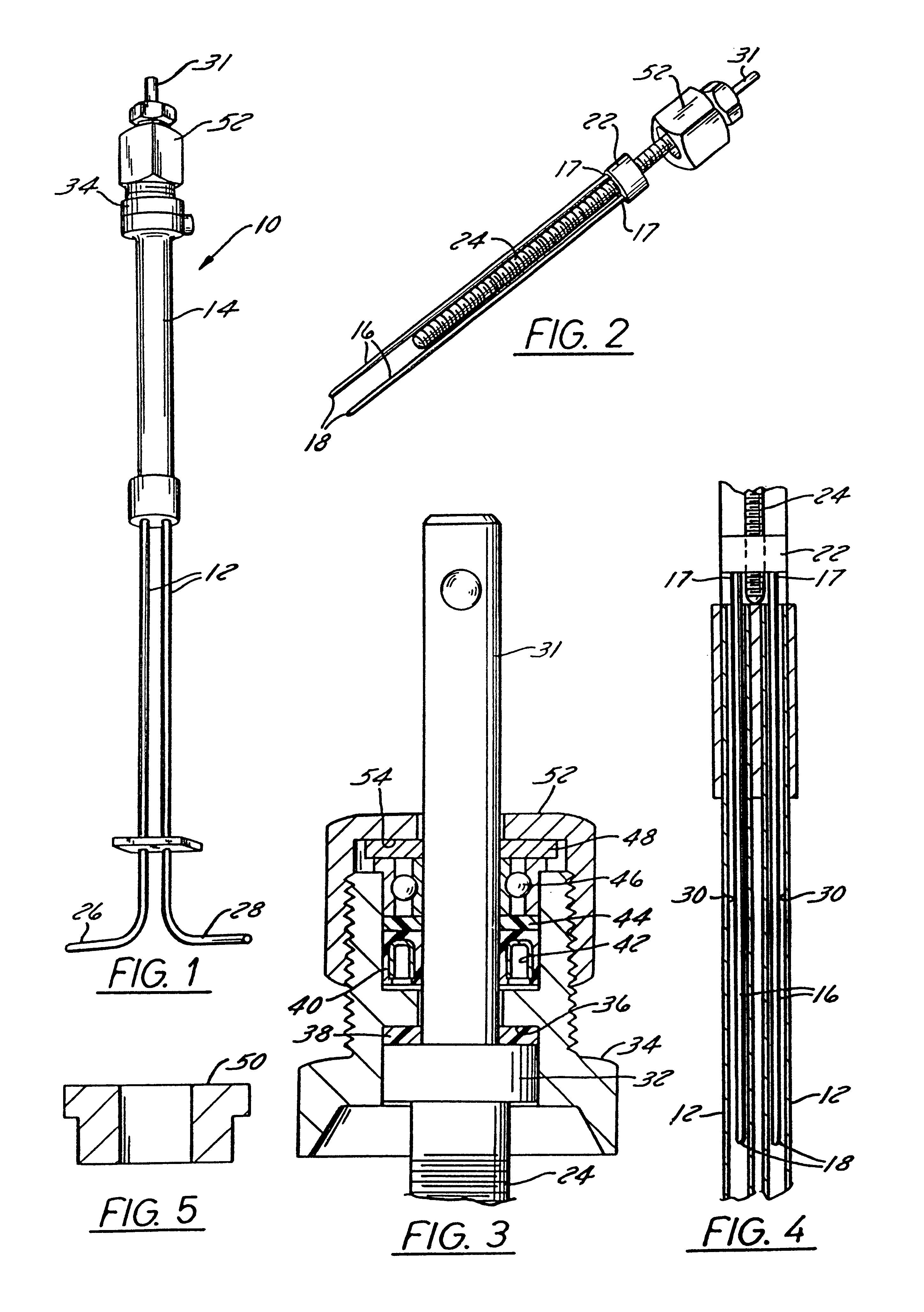
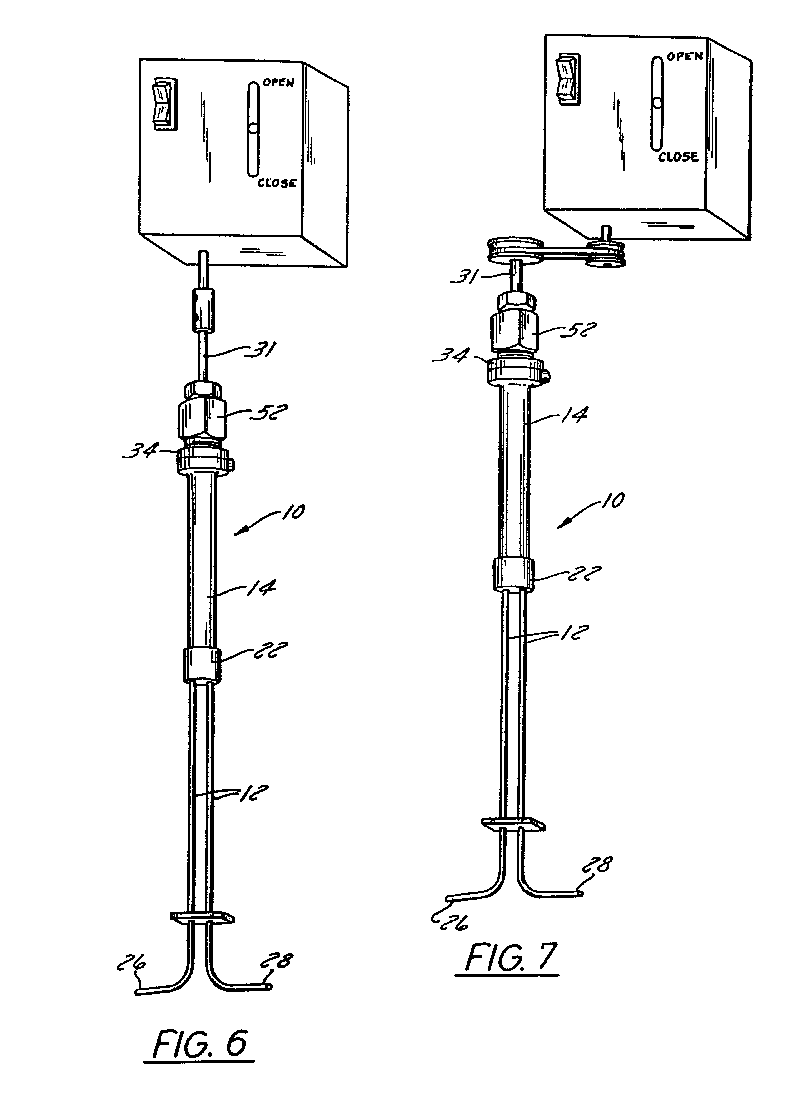
A variable pressure reducing element (VREL .TM.) 10 is used to reduce the pressure and control the flow of high pressure liquids. The device 10 is especially useful for reducing the pressure of steam and hot water samples in a power plant front as high as 5000 psi down to about 50 psi so that the liquid can be safely piped to an analyzer instrument or handled manually for a grab sample.

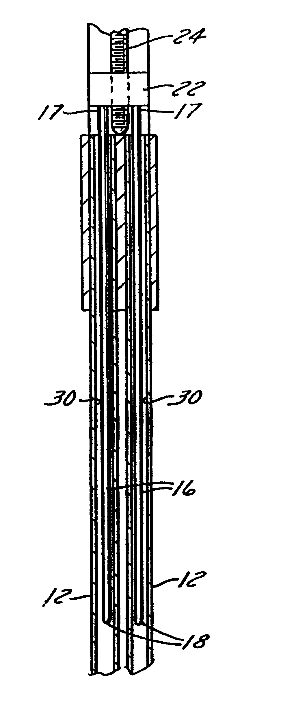
The VREL 10 is a rod-in-tube pressure reducing, flow control device comprising two stainless steel tubes 12 joined to one end of a larger tube or barrel 14. A pair of tapered rods 16 .[.is.]. .Iadd.are .Iaddend.inserted into the two tubes 12. One end 17 of each rod 16 is connected to a threaded ring 22 on a threaded guide screw 24 within the barrel 14. The other end 18 of each rod 16 is rounded. Between the ends 17 and 18, the rod 16 is smoothly tapered from a relatively wide diameter at the end 17 which is connected to the threaded ring 22 down to a relatively narrow diameter at the rounded end 18 of...


PUM

PropertyMeasurementUnit
pressureaaaaaaaaaa
diameteraaaaaaaaaa
frictionaaaaaaaaaa

Abstract

A variable pressure reducing device for reducing high pressure in steam and hot water samples forces the liquid through an annular passageway between a pair of rods within a complementary pair of tubes. The flow rate through the rod-in-tube device, or the pressure drop across the device, is adjustable by means of a rotatable guide screw for adjusting the position of the rods within the tubes. The rods are tapered to provide a smooth flow of liquid through the device. The seal around the guide screw is self energized by means of a seal jacket between a valve gland and a stem portion of the guide screw constructed so that the biasing force of a spring on the seal jacket is supplemented by pressure from liquid flowing through the device The guide screw is centered within the valve gland to keep the guide screw properly aligned, particularly when the device is used with a motor for rotating the guide screw to adjust the position of the rods.

Description

BACKGROUND OF THE INVENTION1. Field of the InventionThis invention relates to a variable pressure reducing device to reduce the pressure and control the flow of high pressure liquids. In particular, the invention relates to a rod-in-tube-type pressure reducing device with an improvement in construction of the rods to smooth the flow of liquid through the device and an improvement in the sealing means to provide easier adjustability of the device.2. Background of the ArtNumerous applications of high pressure fluid systems require, at some point in the system, reduction of the pressure to allow safe handling of the fluid. For instance, a sample withdrawn from a steam and hot water system in a power plant must be reduced in pressure before the sample can be introduced into analyzing instrumentation or handled safely by plant personnel. A number of devices are used in the power plant industry to reduce the high pressure of steam and hot water, such as fixed orifice valves or pressure re...

Claims


Application Information

Patent Timeline
Patent Type & Authority Patents(United States)
IPC IPC(8): F15D1/02F15D1/00G01N1/20
CPCF15D1/02G01N1/2035
Inventor HENSZEY, RICHARD R.WEISS, BRUCE W.
Owner SENTRY EQUIP
Why Eureka
Try Eureka