Virtual memory address translation mechanism with controlled data persistence

a technology of virtual memory address and data persistence, applied in the field of virtual memory address translation mechanism with controlled data persistence, can solve the problem that the access of a particular program which holds the key is also at cache speed, and achieve the effect of facilitating journalling and related data protection and less prone to address errors

Inactive Publication Date: 2001-07-31
IBM CORP
View PDF30 Cites 94 Cited by
  • Summary
  • Abstract
  • Description
  • Claims
  • Application Information

AI Technical Summary

Benefits of technology

It is another object of the invention to provide such a memory subsystem which is less prone to addressing errors due to the use of incorrect translation tables.
It is

Problems solved by technology

However, a further result is that even though data is shared, access

Method used


Image

  • Virtual memory address translation mechanism with controlled data persistence
  • Virtual memory address translation mechanism with controlled data persistence
  • Virtual memory address translation mechanism with controlled data persistence

Examples


Embodiment Construction

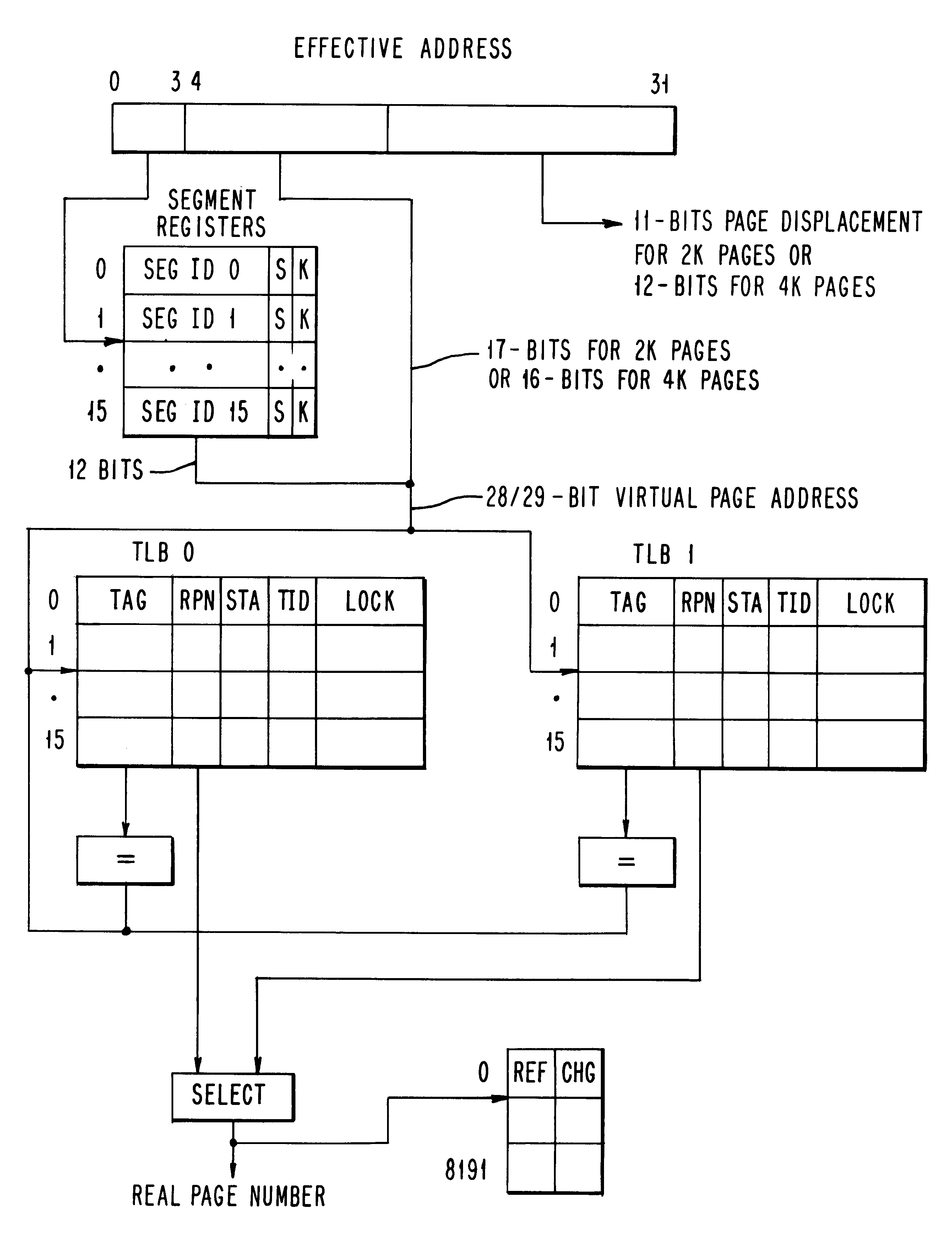
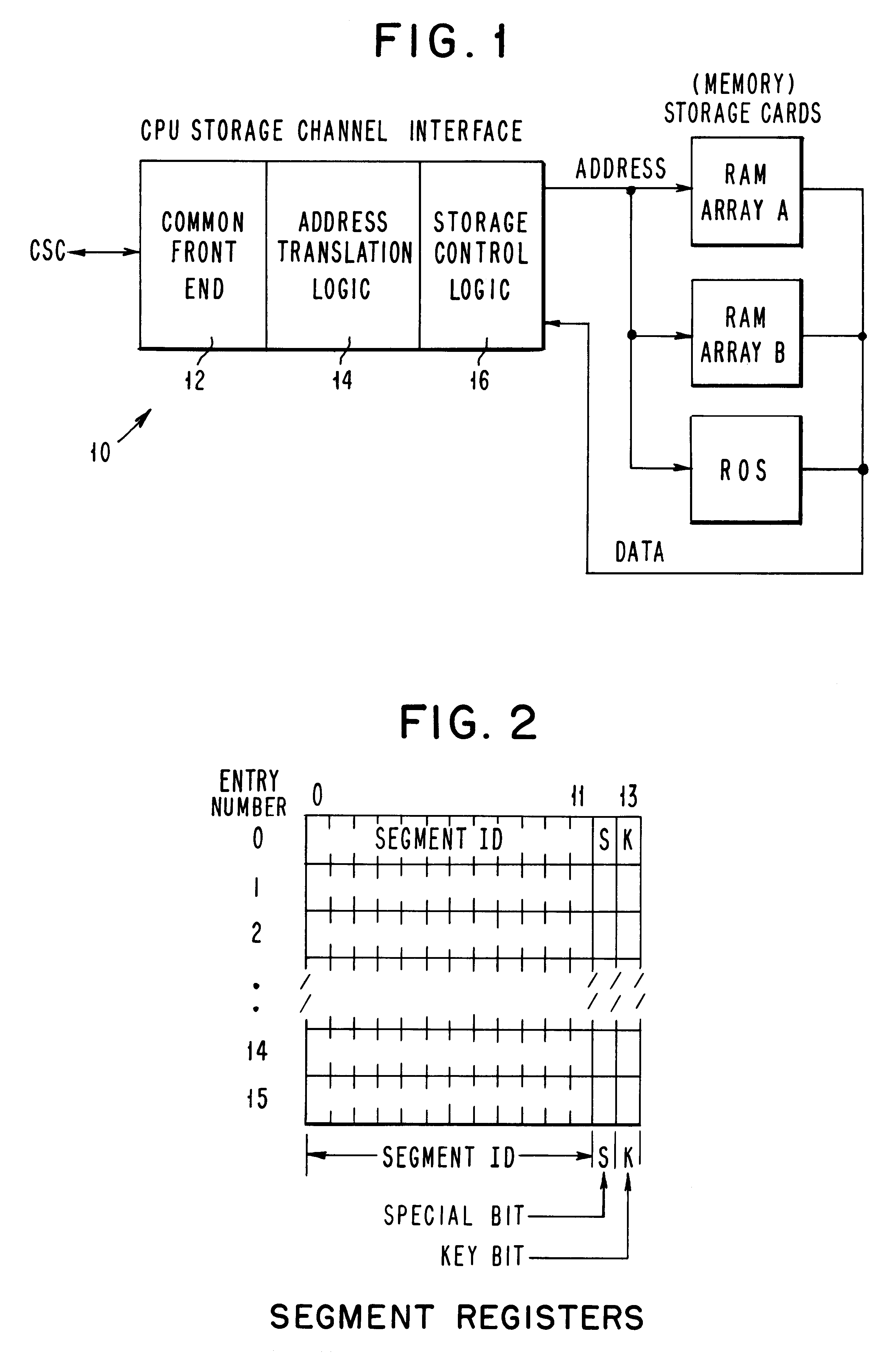
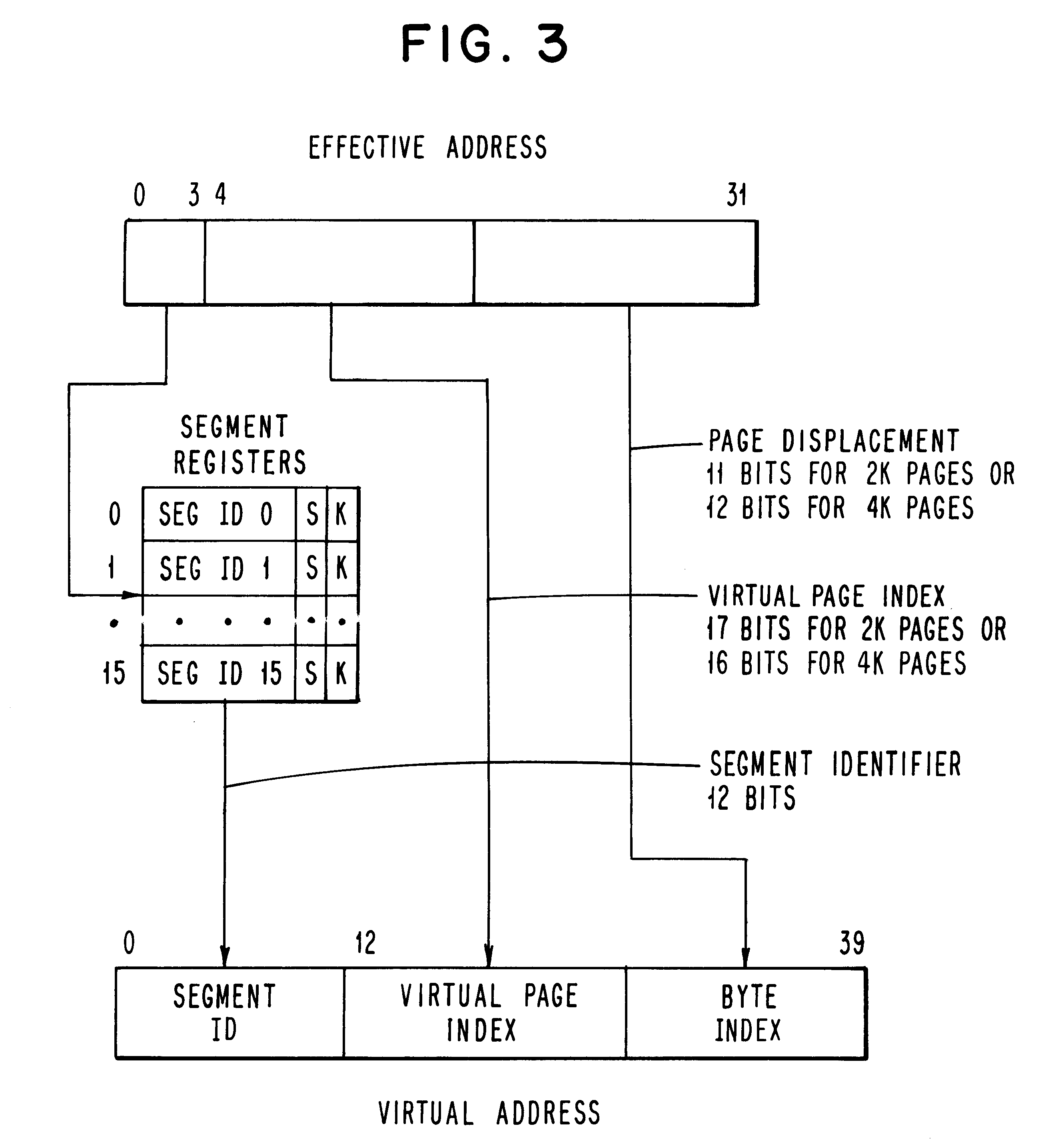
The objects of the present invention are accomplished in general by the herein disclosed storage controller that attaches to a host CPU Storage Channel which implements the address translation architecture described in general terms previously, and which will be described in greater detail subsequently. The translating mechanism contains the logic required to interface with up to 16M bytes of storage. Storage can be interleaved or non-interleaved, and static or dynamic. The translation mechanism is functionally divided into three sections (see FIG. 1). The CPU storage channel interface (CSC) 10 logic consists of the Common Front End (CFE), section 12 which provides the proper protocol from the storage channel to the Address Translation Logic 14 and Storage Control Logic 16. All communication to and from the storage channel is handled by this logic. The Address Translation Logic provides the translation from a virtual address received from the storage channel to a real address used t...


PUM


Abstract

A memory address translation and related control system for performing the dual functions of converting virtual memory addresses generated by the CPU into real memory addresses in a highly efficient and versatile manner and for controlling certain memory functions such as journalling. The address translation function comprises two steps, the first comprising converting the virtual address into a second virtual address or an effective address and finally the step of converting the effective address into a real memory address. The first step utilizes a set of special registers addressable by a small field to the CPU generated virtual address which converts the virtual address into an expanded form. The second or effective address is then used as the subject of the second or address translation step. To greatly enhance the translation of frequently used virtual addresses, a special set of translation tables referred to herein as a Translation Look-Aside, Buffer (TLB) contain current effective to real address translations for use where frequently referenced addresses are requested. The TLBs are addressed using a subset of the effective address whereupon the contents of the addressed TLB is examined for a match with the effective address. If the addresses match a successful address translation is possible and the real address stored in the address field of the TLB is available for system use. If the desired effective address is not present in the TLB, the page frame tables stored in main memory are accessed and searched for the desired effective address and if found the associated real address is accessed. Further a special data field is provided in both the TLBs and the page frame tables in main memory wherein a bit is provided for each line in the referenced page at a given effective to real address translation which bits may be used to indicate when a line of data has been accessed or altered.

Description

BACKGROUND OF THE INVENTION1. Field of the InventionThe present invention relates generally to computer memory subsystems and more particularly to such a memory subsystem organized into what is known in the art as a virtual memory. Still more particularly, the invention relates to an apparatus for converting virtual addresses into real memory addresses and for effecting certain unique control functions within the memory hierarchy.In most modern computer .[.system.]. .Iadd.systems.Iaddend., when a program is executing, it frequently attempts to access data or code which resides somewhere in the system (that is, in some level of the cache / main store / Direct Access Storage Device (DASD) storage hierarchy or even at another node in a distributed system network). For the most primitive system, consider what the program must understand in order to make this access.Where is the data (or code)? The location will generally determine what kind of address must be used for the access (e.g. main ...

Claims


Application Information

Patent Timeline
IPC IPC(8): G06F12/10G06F13/00G06F11/07G06F12/00G06F12/14
CPCG06F11/073G06F11/0772G06F11/0781G06F12/1036G06F12/1475G06F2212/683
Inventor CHANG, ALBERTCOCKE, JOHNMERGEN, MARK F.RADIN, GEORGE
Owner IBM CORP
Why Eureka
Try Eureka