Resistance projection welding system and method for welding a fastener element to a workpiece

a technology of resistance projection and welding system, which is applied in the field of resisting projection weld nut welding system and method, can solve the problems of projection weld nut not being known when a projection weld nut is used, inability to extend the bolt through the aperture of the workpiece, and uneven surface of the projection weld nut inadequately penetrates the workpiece, so as to prevent the shorting of the welding electrod

Inactive Publication Date: 2002-03-26
CECIL DIMITRIOS G
View PDF27 Cites 16 Cited by
  • Summary
  • Abstract
  • Description
  • Claims
  • Application Information

AI Technical Summary

Benefits of technology

Still yet a further object of the present invention is to prevent the shorting of the welding electrode by avoiding the application of electrical power to an electrode not engaged with a projection weld nut.
Still yet another object of the present invention is to prevent the subsequent application of electric power to a projection weld nut presently welded to a workpiece.

Problems solved by technology

A problem arises when the projection weld nut is loaded onto the workpiece in an upside down or an inverted position.
This problem can occur when using a vibrational nut feeder for supplying the projection weld nuts.
Consequently, the smooth surface of the projection weld nut inadequately penetrates the workpiece due to the lack of heat generated.
A primary disadvantage associated with existing resistance projection weld nut welding systems is the fact that it is unknown when a projection weld nut has been welded upside down or laterally out of position with respect to an aperture on the workpiece.
This disadvantage exposes itself when a failure occurs during an attempt to screw a bolt into the welded projection nut or subsequently when the nut is loaded.
If the projection nut was welded out of position, it is impossible to extend the bolt through the aperture on the workpiece.
A second problem in resistance welding is in controlling the weld process satisfactorily in order to consistently produce good welds.
Many of these variables are difficult to consistently control because of contaminants at the faying surfaces such as dirt, grease, oil or paper.
Improper welding conditions can cause defective welds due to expulsion and low or over penetration of the weld nut projections.
Expulsion occurs when an excessive application of power blows out the projections at the faying surfaces.
Over penetration results from the weld current being too strong or applied for too much time.
Too little power causes low penetration.
Defectively welded projection weld nuts have distinguishing features from good welds such as being weaker, being misaligned, weld expulsion bonded to its internal threads rendering the projection nut non-usable, and other defects.
These feedback systems are disadvantageous because they do not directly detect physical characteristics of the weld itself, but instead rely upon detection of secondary parameters.
This can lead to poor weld quality when uncontrolled parameters vary from nominal operating conditions.
A product that has weak welds can fail to perform under extreme stress, fail at some point during the course of normal operation or can break after other parts have been welded to it.
Obviously, it is very expensive and impractical to repair or replace a bad weld after a unit has been welded together and assembled in a vehicle.
If the air bag is supported by defective welds, it may not perform its intended function.
Finally, if the incorrectly welded projection nut has enough strength to allow the required torque at assembly to hold, it can fail later while in use due to structural vibrations or other stresses transferred to this weak joint.
A further obstacle in resistance welding occurs when an electrode becomes fused to a welding surface after completion of a weld.
If the welding system does not detect the stuck gun before attempting to move the electrodes from a closed welding position to an opened position, extensive damage to the electrodes, weld gun, a work cell, and even human weld operators may occur.
The strength of the weld between a projection weld nut presently welded to a workpiece is substantially weakened with the application of subsequent electric welding power.
The subsequent welding power causes the projections to overheat, and thus become brittle.

Method used


Image

  • Resistance projection welding system and method for welding a fastener element to a workpiece
  • Resistance projection welding system and method for welding a fastener element to a workpiece
  • Resistance projection welding system and method for welding a fastener element to a workpiece

Examples


Embodiment Construction

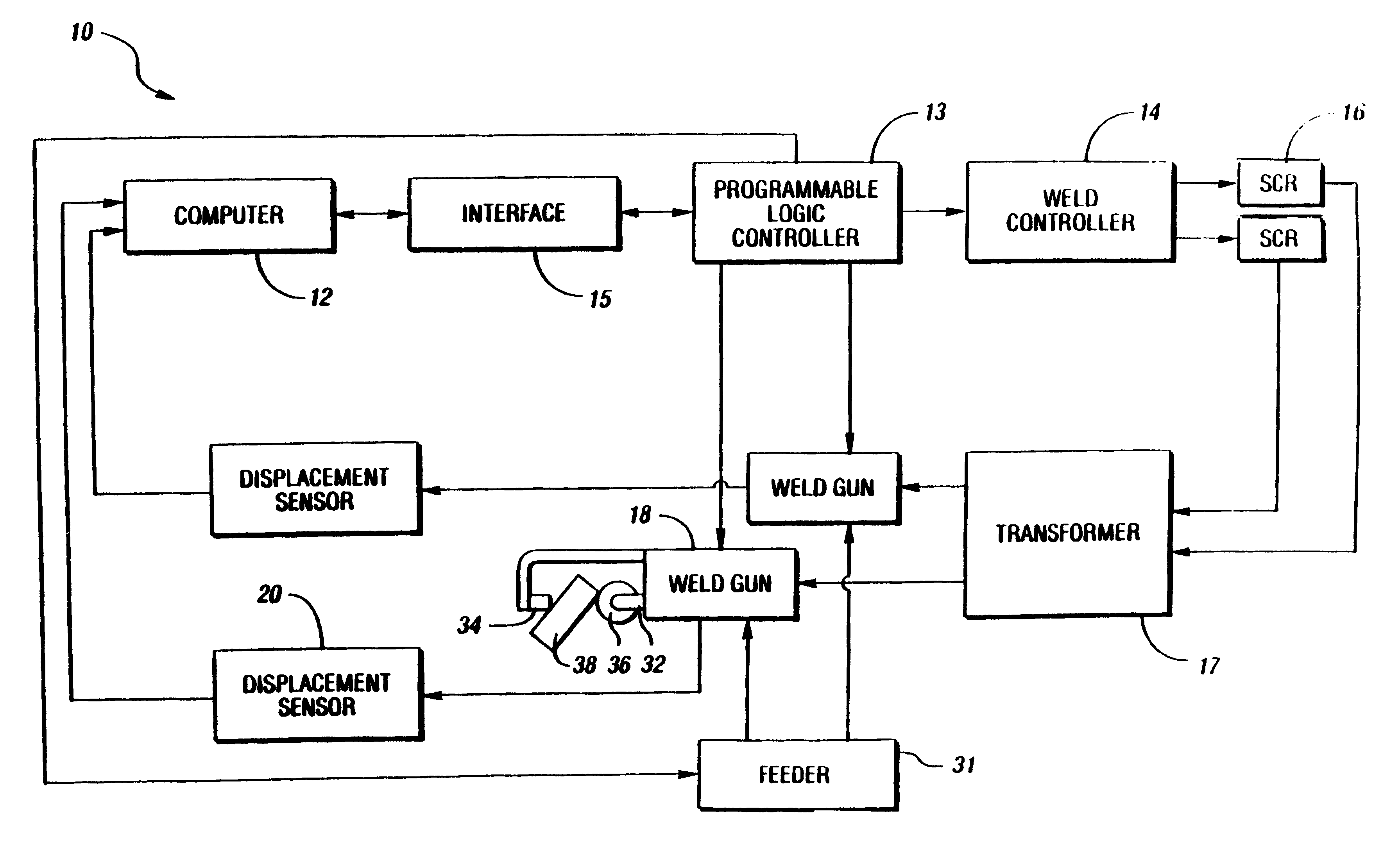
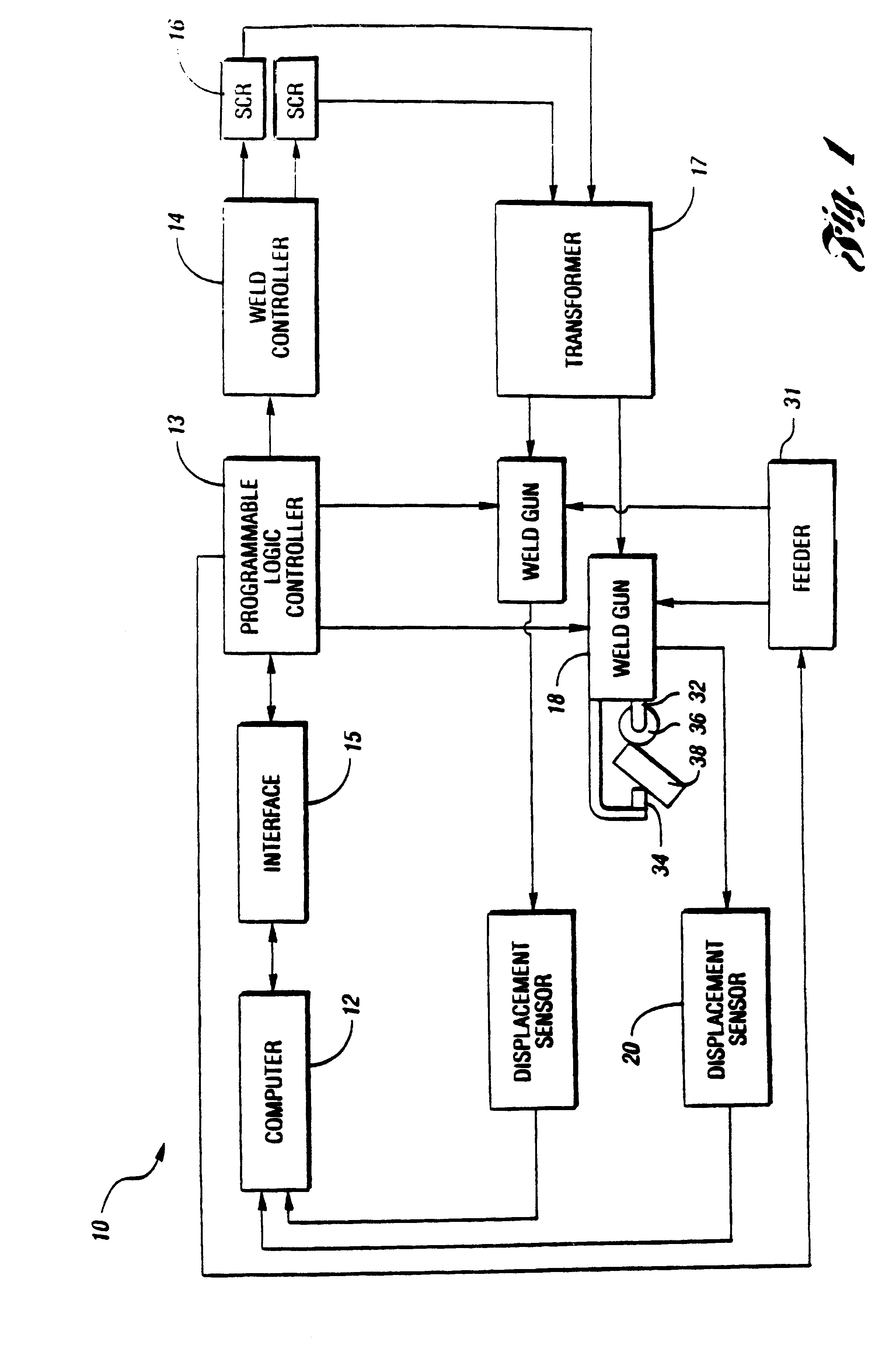
FIG. 1 illustrates a block diagram of a resistance projection welding system 10. Welding system 10 includes a computer 12, a programmable logic controller (PLC) 13, a weld controller 14, an interface 15, a silicon controlled rectifier (SCR) 16, a transformer 17, a weld gun 18, and a displacement sensor 20. As is well known in the art, welding system 10 includes many readily available components. For example, PLC 13 may be obtained from a manufacturer such as Allen Bradley. Weld controller 14 is manufactured by Weltronics, Medar, or Square D. Farrah makes SCR 16. Roman produces transformer 17 and weld gun 18 can be obtained from Milco, Savair, Grossel, OHMA or Centerline.

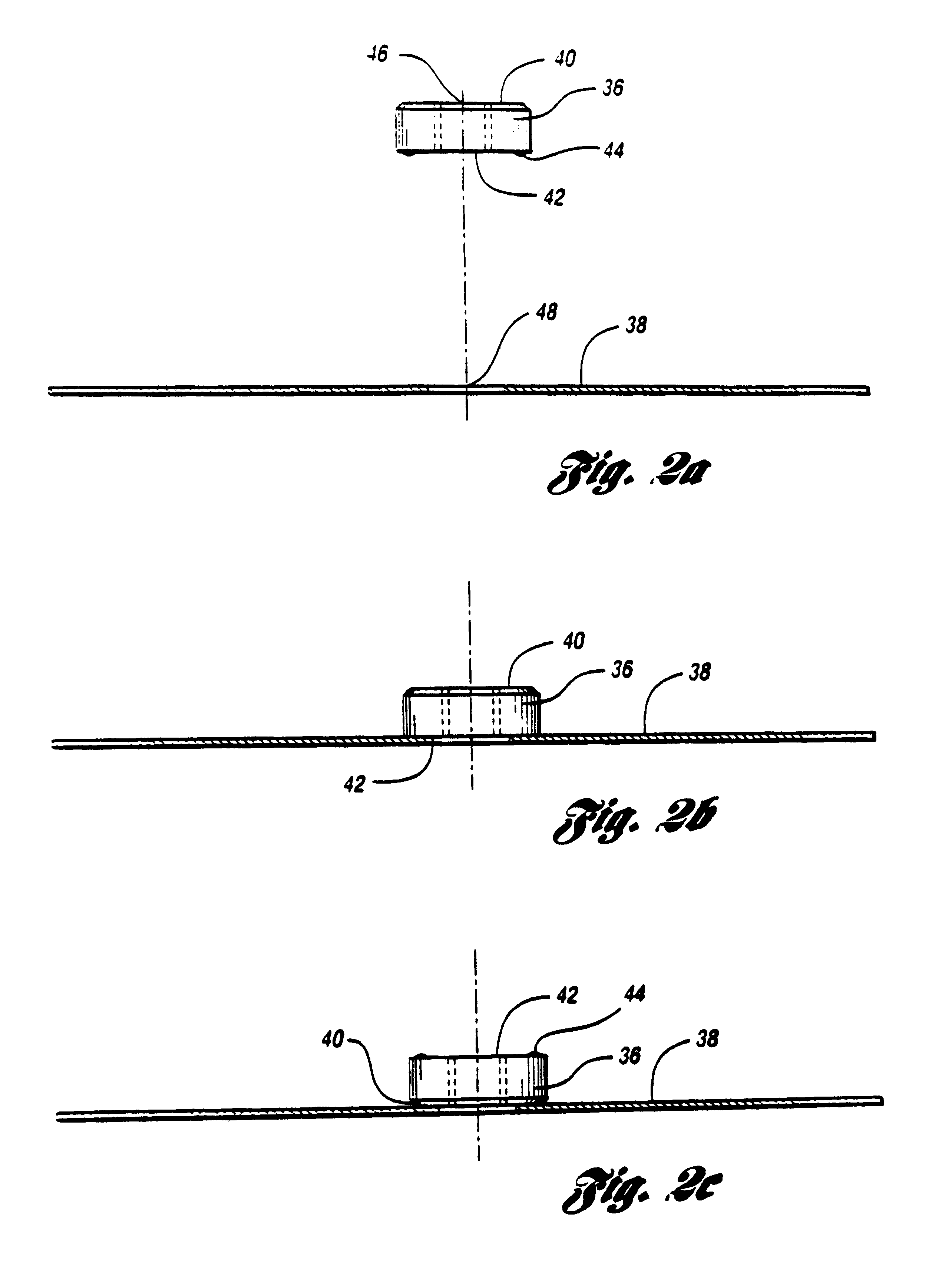
Weld gun 18 has a first electrode 32 and a second electrode 34. First electrode 32 engages a projection weld nut 36. Second electrode 34 engages a workpiece 38. Projection weld nut 36 is to be welded onto workpiece 38. As is known in the art, weld gun 18 may be a single electrode system.

According to the preferred pro...


PUM

PropertyMeasurementUnit
distanceaaaaaaaaaa
poweraaaaaaaaaa
welding poweraaaaaaaaaa

Abstract

A system and method is disclosed for monitoring and controlling a resistance projection welder for welding a projection weld nut to a workpiece. A displacement sensor measures the displacement of a welding electrode of a weld gun in real time during the welding procedure. A computer is coupled to the displacement sensor and determines whether the projection weld nut is correctly loaded between the workpiece and the welding electrode. The computer instructs a programmable logic controller (PLC) to trigger a weld controller to apply power to the welding electrode if the projection weld nut is correctly loaded onto the workpiece. The computer instructs the PLC to inhibit power if it determines the projection weld nut to be inverted, missing, or misaligned in order to allow for the removal and replacement of the projection weld nut. The computer further instructs the PLC to control and terminate the power to the welding electrode in real time in order to form a projection weld between the projection weld nut and the workpiece that is substantially similar to a predetermined projection weld. The computer processes the displacement data and provides a fault signal when the projection weld is unacceptable. A marker marks the unacceptable workpieces in response to the fault signal.

Description

TECHNICAL FIELDThe present invention relates generally to a welding system, and more particularly to a resistance projection weld nut welding system and method.BACKGROUND ARTIt is a common manufacturing practice to secure nuts directly to sheet metal pieces through a welding process. In the manufacture of motor vehicles today, there are virtually hundreds of applications for such "projection weld nuts" which form attachments for air bag supports, door hinges, motor and transmission mounts, safety belts, and many other industrial applications.Conventional resistance projection welding techniques employ a method by which metal workpieces are joined together at one or more predetermined points such as projections, embossments, or intersections. Workpieces are held together at the predetermined points under force by one or more electrodes. The contacting points are heated by a pulse of high amperage welding current generated by contact with an electrode. The resistance to the flow of we...

Claims


Application Information

Patent Timeline
Patent Type & Authority Patents(United States)
IPC IPC(8): B23K11/25B23K11/14
CPCB23K11/14B23K11/253
Inventor CECIL, DIMITRIOS G.
Owner CECIL DIMITRIOS G
Why Eureka
Try Eureka