Downhole equipment, tools and assembly procedures for the drilling, tie-in and completion of vertical cased oil wells connected to liner-equipped multiple drainholes

a technology of vertical cased oil wells and assembly procedures, applied in the direction of drilling pipes, drilling/well accessories, drilling directional drilling, etc., can solve the problems of no safety controls and minimal operational flexibility

Inactive Publication Date: 2002-10-08
HALLIBURTON ENERGY SERVICES INC
View PDF120 Cites 28 Cited by
  • Summary
  • Abstract
  • Description
  • Claims
  • Application Information

AI Technical Summary

Benefits of technology

The present invention addresses the problem of drilling, cementation and tie-in by pressure-tight connections to a casing of twin or multiple drainholes of medium to short radius of curvature (typ...

Problems solved by technology

The simplest, which allows only commingled flow from or into all drainholes simultaneously, does not even requires any add...

Method used


Image

  • Downhole equipment, tools and assembly procedures for the drilling, tie-in and completion of vertical cased oil wells connected to liner-equipped multiple drainholes
  • Downhole equipment, tools and assembly procedures for the drilling, tie-in and completion of vertical cased oil wells connected to liner-equipped multiple drainholes
  • Downhole equipment, tools and assembly procedures for the drilling, tie-in and completion of vertical cased oil wells connected to liner-equipped multiple drainholes

Examples


case 1 (

TWIN WHIPSTOCK)

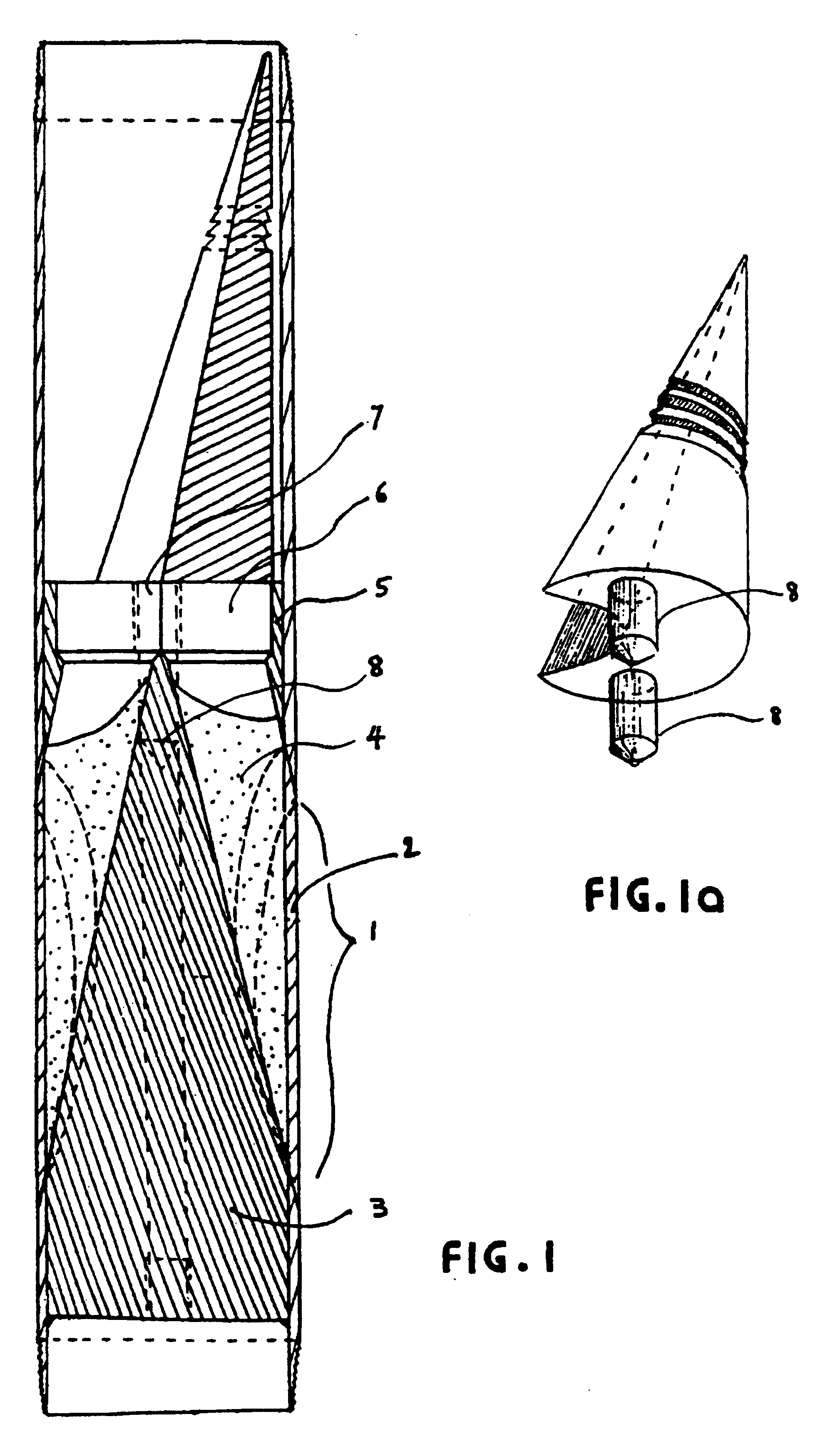
In Case 1 a vertical well is drilled to a depth slightly greater than that of the common kick-off depth of the drainholes. The casing string is made-up by including a special joint immediately above the conventional casing shoe and float collar. This casing joint shown on FIG. 1 includes two elliptical windows (1) machined at the desired kick-off angle, typically about 2 degrees oriented downward from the vertical.

These windows are plugged up with a drillable material (an Aluminum plate (2), for instance) machined to conform with the cylindrical surfaces of the casing. A twin whipstock (3), of hardened metal, is securely fastened to the casing joint, for instance by welding. It provides a curved guiding path from a guide plate above to each of the two plugged windows. For added strength, a portion of that curved guide may be partly filled with cement (4) or other drillable material. The guide plate (5), on top of the whipstock, presents four vertical cylindrical holes...

case 2 (

TWIN DEVIATED HOLES)

In Case 2, from a vertical cased well drilled and cemented by conventional techniques, the casing shoe is drilled out and two short (ca. 50 ft long) smaller diameter twin deviated holes are drilled through the bottom of the vertical well. This uses, for instance, a bit (16) driven by a downhole motor (17) connected to a bent sub (18), in the type of downhole assembly commonly used for drilling horizontal wells (see FIG. 2).

With deviation angles of only a few degrees from the vertical, the separation between the two holes is only of a few feet at the bottom and of a few inches at the top. Consequently, it may be advantageous in some formations, to start the drilling operation by first under-reaming a single large-diameter short hole below the casing shoe, from which the twin small-diameter drainholes are then started, with opposite orientations. Several other available techniques are also familiar to those skilled in the art of drilling oil wells and may be used t...

case 3 (deviated cased well)

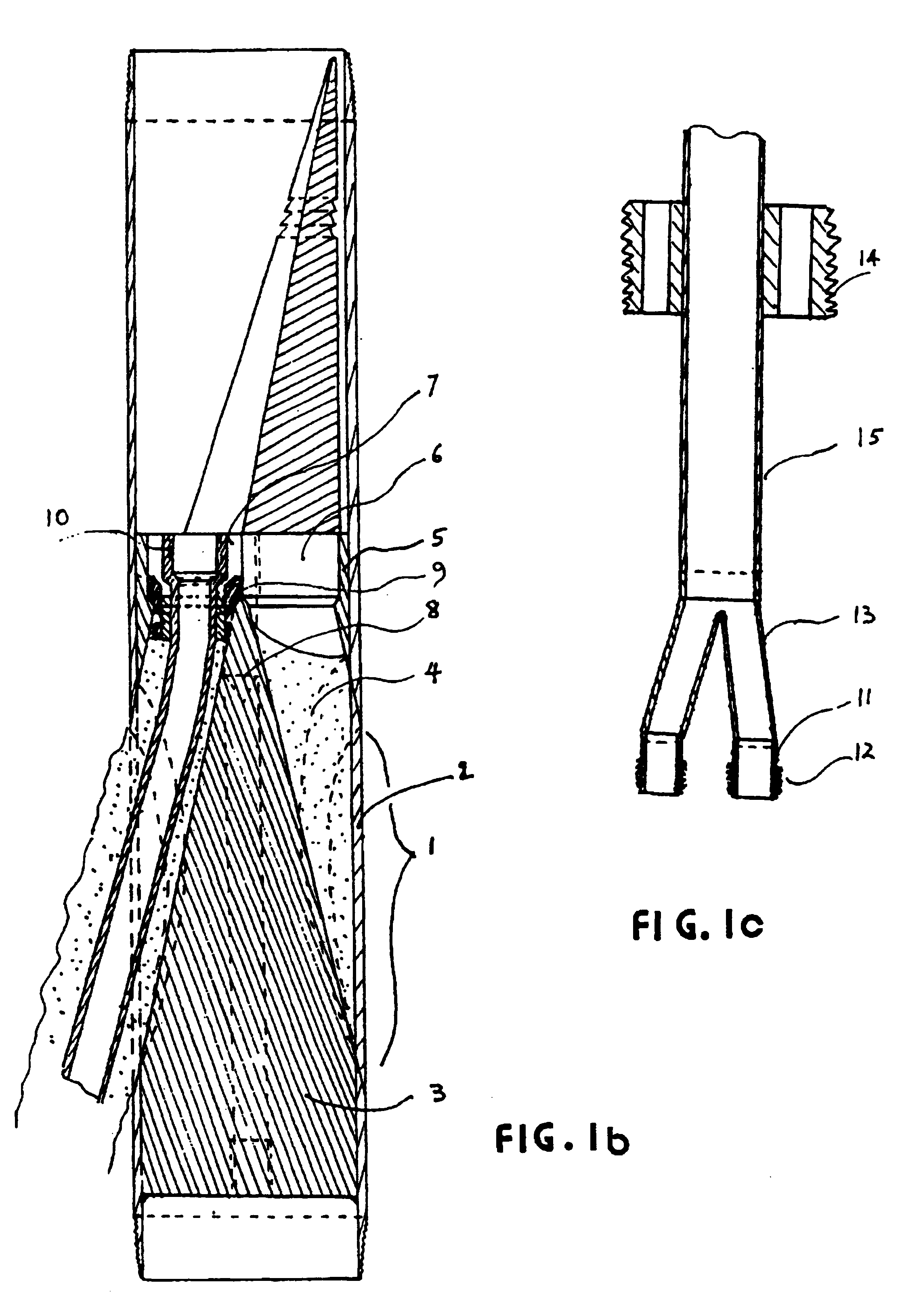
.Iadd.Case 3 includes a special casing joint equipped with a drillable packer and retrievable whipstock for drilling and completion of a side-tracked hole. .Iaddend.In Case 3, a vertical well is drilled, with its lower 50 ft deviated at the angle required to kick-off a horizontal drainhole and oriented in the direction selected for the drainholes. A special casing string is made-up, run-in and cemented by known techniques into the vertical and deviated portions of the hole. It consits of a shoe, a float collar and a special casing joint .[.(FIG. 3).]. .Iadd., see FIGS. 3a-3c, .Iaddend.located at a depth slightly above that of the start of the hole deviation. This casing joint presents an elliptical window machined into the casing with a downward orientation of a few degrees from the vertical. .[.The.]. .Iadd.As previously shown in FIG. 1, the .Iaddend.window (1) is again plugged off with a drillable plate (2) made, for instance, of a soft metal and shaped to generally conform with t...


PUM


Abstract

Single horizontal wells drilled through heterogeneous reservoirs are capable of greater oil productivity than vertical wells, often with lower produced GOR and WOR. Multiple drainholes tied-in to a vertical cased well are even more beneficial. Completion of such drainholes in many sandy reservoirs must use cemented liners. Well configurations comprising multiple drainholes liners, each of them tied-in to a vertical casing by pressure-tight connections require novel technologies making use of some novel downhole equipment, tools and procedures for drilling, tie-in and completion of such wells. These may be for newly-drilled wells or may be obtained by re-entry into an existing vertical cased well. Specific equipment, including novel casing joints, whipstocks, intermediate liners and tubing completion assembly components applicable to new wells are described herein. Equipment comprising novel casing inserts and patches applicable to re-entry wells, and the corresponding tubing completion assembly components for a variety of well exploitation modes are also described, together with the required tools and procedures. The liners of the drainholes are such that known well logging and cleaning tools may be used throughout the well's life. The various tubing completion assemblies can all be run-in and installed in a single trip. They allow either commingled flow from all drainholes or selective injection into some drainholes while others are under production. They are adapted to a variety of reservoir pressure conditions and of oil types, including heavy oil produced by sequential "huff and puff" steam injection.

Description

FIELD OF THE INVENTIONHorizontal wells have been used extensively in heterogeneous reservoirs to intersect fractures and / or to reduce the detrimental effects of gas coning and water coning. It has been shown that such wells are capable of higher oil production rates than vertical wells drilled in the same reservoir. In most cases, the higher productivity more than offsets the higher cost of drilling and completion of the horizontal well. Theory predicts that the use of multiple horizontal drainholes correspondingly multiplies the total well productivity. Indeed many vertical cased wells connected to twin or multiple horizontal drainholes of medium (500-200 ft) and short (150-40 ft) radius of curvature have been successfully used in compact oil reservoirs, such as the Austin Chalk, in which open hole completion of the drainholes is applicable.In many clastic reservoirs, however, the strength of unconsolidated sands or of friable sandstones may be insufficient to keep horizontal drain...

Claims


Application Information

Patent Timeline
IPC IPC(8): E21B7/04E21B7/06E21B43/00E21B43/30E21B43/24E21B41/00E21B43/14E21B43/16E21B43/10
CPCE21B7/061E21B41/0035E21B41/0042E21B43/10E21B43/14E21B43/24E21B43/305
Inventor GONDOUIN, MICHEL
Owner HALLIBURTON ENERGY SERVICES INC
Why Eureka
Try Eureka