Crankcase bypass system with oil scavenging device

a technology of bypass system and crankcase, which is applied in the direction of combustion air/fuel air treatment, machine/engine, fuel intake, etc., can solve the problems of ineffective valves, deficient standard pcv valves, and insufficient by-pass gas flow under the full range of engine performance,

Inactive Publication Date: 2002-08-20
MAHLE ENGINE COMPONENTS USA
View PDF25 Cites 35 Cited by
  • Summary
  • Abstract
  • Description
  • Claims
  • Application Information

AI Technical Summary

Problems solved by technology

A phenomenon called "engine blow-by" unfortunately assures that some of the combustion gases will escape the combustion chamber and flow into the engine crankcase, irrespective of the quality of the engine and/or the piston rings employed.
The standard PCV valve, however, has been deficient in several respects.
For example, the valve has not consistently provided satisfactory by-pass gas flows under the full range of engine performance, i.e., from idle through full wide-open throttle conditions, and particularly as impacted by wear due to operation.
For example, under very high rpm conditions, the valve has often been ineffective to fully relieve crankcase pressure, particularly under high engine loads or low vacuum conditions.
In addition, the typical PCV valve system has been ineffective to separate...

Method used


Image

  • Crankcase bypass system with oil scavenging device
  • Crankcase bypass system with oil scavenging device
  • Crankcase bypass system with oil scavenging device

Examples


Embodiment Construction

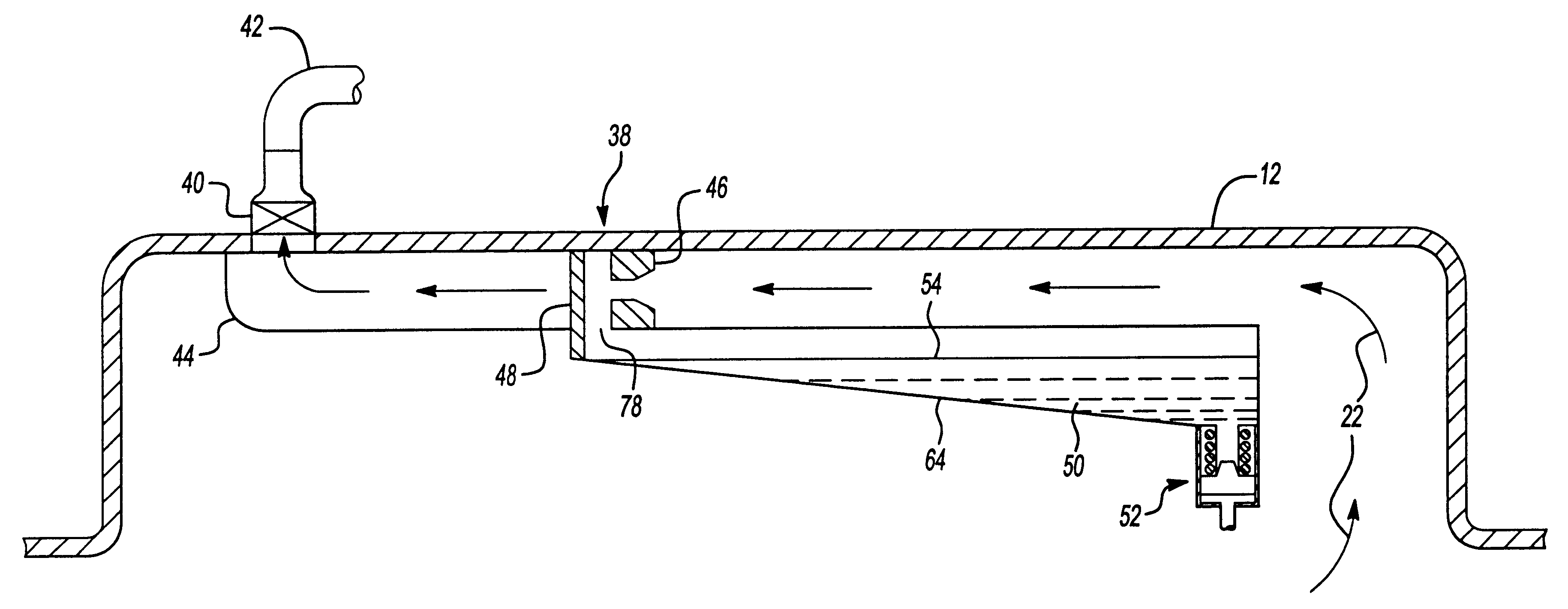
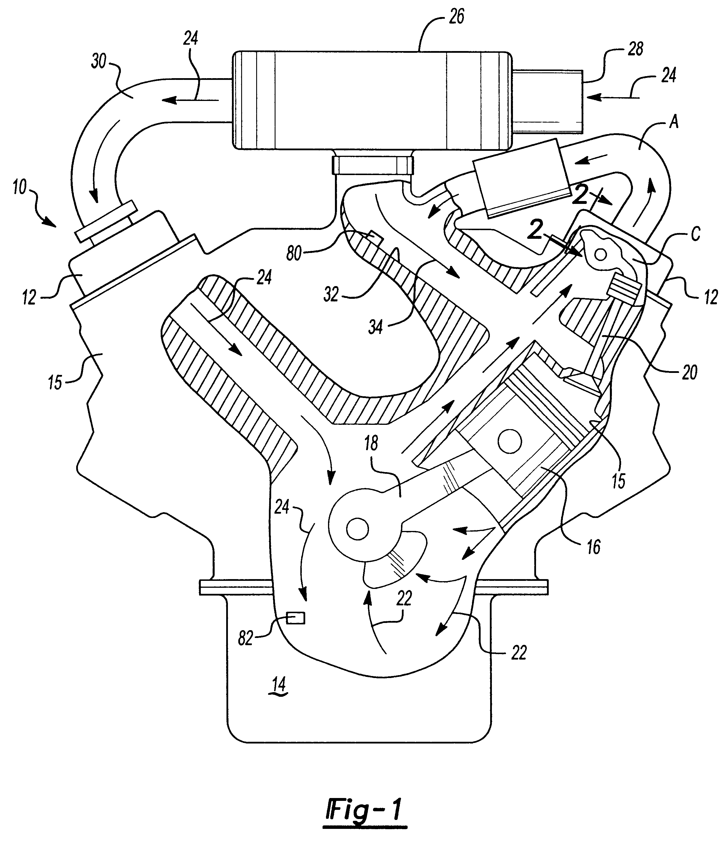
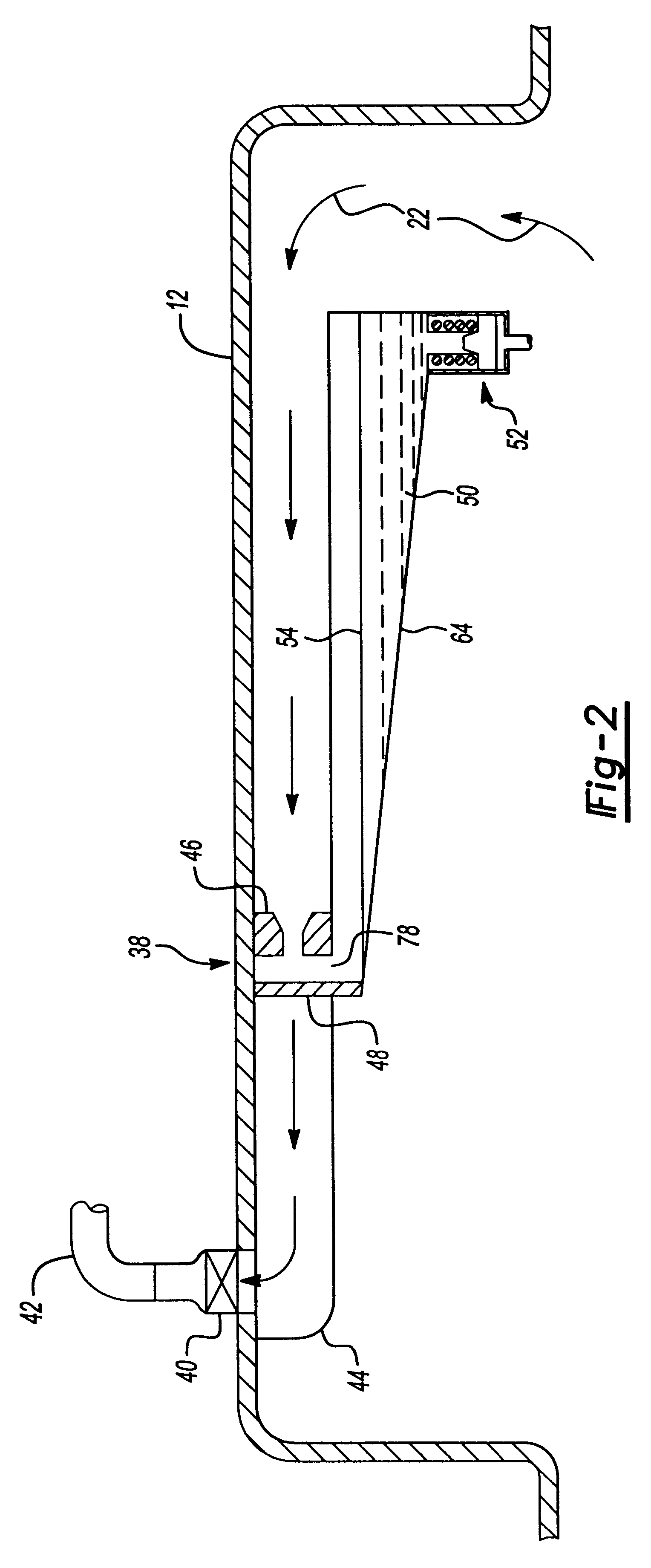
Referring initially to FIG. 1, a schematic view of an internal combustion engine 10 is presented. Portions of the engine 10 are cut away to reveal one bank of cylinders 15 positioned under a rocker cover 12 to reveal the paths or movements of fresh air (arrows 24) and bypass gas flow stream (arrows 22) through various parts of the engine. An oil sump 14 is provided at the base of the engine 10, and a representative piston 16 reciprocates within the cylinder 15, the piston 16 being connected to a crankshaft connecting rod 18, as will be appreciated by those skilled in the art. Sets of intake and exhaust valves 20 admit air and release exhaust gases, respectively, into and out of the engine 10.

At the upper portion of the engine 10 is an air filter canister 26 adapted to admit fresh air 24 into an air intake nozzle 28. The fresh air 24 is filtered in the canister 26, and then travels through a hose or conduit 30 into one of the banks of cylinders 15. Although shown only schematically, ...


PUM


Abstract

An engine crankcase bypass system includes a scavenging mechanism for the collection and removal of oil entrained in engine bypass gases that include unburned gasoline fuel and water vapors. The improved bypass system, designed to replace a standard PCV (positive crankcase ventilation) system, senses manifold and crankcase vacuum pressures, and via utilization of either an electronic or mechanical valve provides continuous adjustments of bypass gas flows for the maintenance of a constant gas flow sufficient to exceed normal engine bypass flow rates. A deflector system positioned in a flow stream is designed to extract and separate oil vapor from unburned gasoline fuel and water vapors entrained in the bypass gases. The oil is collected and drained to a temporary reservoir for subsequent re-entry into the oil sump of the engine. The fuel and water vapors are immediately returned to the intake manifold of the engine for reburning of the fuel.

Description

1. Field of InventionThe present invention relates to engine crankcase ventilation systems adapted to control by-pass gases composed of blow-by gas and fresh air. More particularly, the invention relates to an improved scavenging mechanism for separation of oil from a flow stream of by-pass gases entrained with oil and unburned fuel and water vapors, and to result in improved ventilation flow control.2. Description of the Prior ArtThose skilled in the art will appreciate, contrary to ideal expectations, that combustion gases are not normally confined to the combustion chamber and exhaust manifold areas of an engine. A phenomenon called "engine blow-by" unfortunately assures that some of the combustion gases will escape the combustion chamber and flow into the engine crankcase, irrespective of the quality of the engine and / or the piston rings employed. Engine blow-by occurs on the power stroke of an internal combustion engine; i.e., the normally downward stroke of the piston caused b...

Claims


Application Information

Patent Timeline
IPC IPC(8): F01M13/04F02B75/00F01M13/00F02B75/22F02M25/06F02M35/104F02M35/116F02M35/10
CPCF01M13/04F02B75/22F02M25/06F02M35/10222F02M35/10288F01M2013/0433F02M35/116Y02T10/121Y02T10/12
Inventor HAMELINK, JOSEPH C.HILL, STEPHEN H.
Owner MAHLE ENGINE COMPONENTS USA
Why Eureka
Try Eureka