Noise suppressor apparatus for a gas duct

a tube channel and noise suppression technology, applied in the direction of machine/engine, combustion air/fuel air treatment, etc., can solve the problems of limiting the usability of the broadband noise suppressor, requiring a substantial amount of space to arrange the curved bypass channel, and complex manufacturing of the bypass channel. , to achieve the effect of preventing a dip in the noise suppression effect, compact design and low manufacturing complexity

Inactive Publication Date: 2005-01-27
MANN HUMMEL GMBH
View PDF15 Cites 34 Cited by
  • Summary
  • Abstract
  • Description
  • Claims
  • Application Information

AI Technical Summary

Benefits of technology

To prevent a dip in the noise suppression effect between the three suppression peaks, the present invention uses a variation of the cross-sectional areas of the main flow-through channel to the sum of the bypass flow-through channels. With a suitably small total spiral channel cross-sectional area relative to the cross-sectional area of the main tubular channel, the dips between the three suppression peaks disappear and the noise suppression may be pushed to well over 20 dB.
The noise suppression apparatus with spiral channels according to the present invention allows the noise suppressor to be designed as a broadband noise suppressor with a very compact design which can also be used for suppression of frequencies above 1000 Hz. In one advantageous embodiment of this invention, the main channel is formed by a central pipe with the spiral channels in contact with its outside surface. A low manufacturing complexity is required when the spiral channels are attached as half-shells to the central pipe, which is optionally a continuation of the tubular channel before the branching off of the spiral channels. The inlet and outlet openings of the spiral channels may be formed by apertures in the wall of the central pipe. It is especially advantageous for the inlet and outlet openings of the main channel and the spiral channels to be in a cross-sectional area of the tubular channel which has continuous flow. The spiral channels are thus parallel to the gas flow in the tubular channel and contribute fully toward a smaller pressure drop.

Problems solved by technology

The dip in noise suppression down to less than 10 dB between the three peaks limit the broadband usability of this noise suppressor.
The devices known from the prior art require a substantial amount of space to arrange the curved bypass channels, some of which extend a great distance away from the main channel.
In addition, manufacturing the bypass channels is complex.
In particular in noise suppression of internal combustion engines for motor vehicles, the available space is often very limited, so the known devices are too large and are not suitable for use with automobile engines.

Method used


Image

  • Noise suppressor apparatus for a gas duct
  • Noise suppressor apparatus for a gas duct
  • Noise suppressor apparatus for a gas duct

Examples


Embodiment Construction

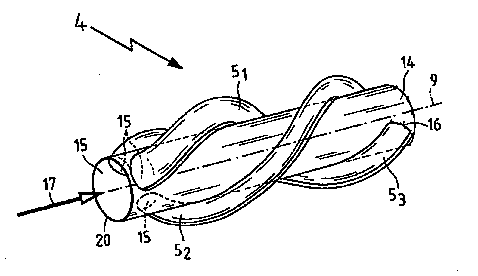
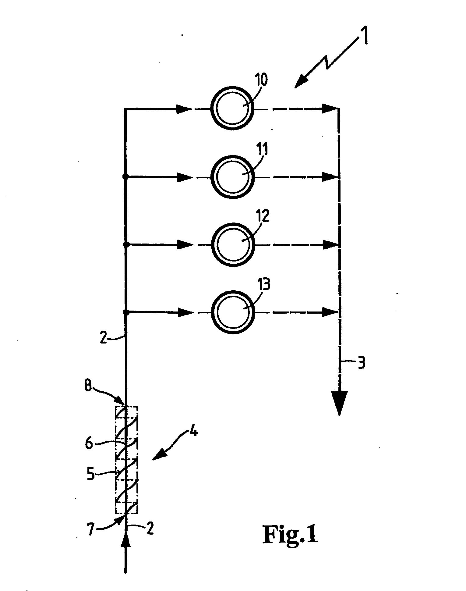
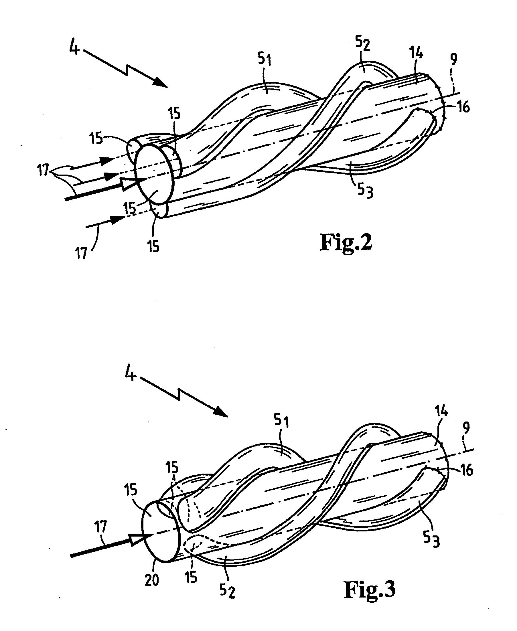
FIG. 1 depicts an internal combustion engine 1 with four cylinders 10, 11, 12, 13, each of which is supplied with fresh combustion air from a common air intake line 2. The exhaust gases from combustion in the cylinders 10 through 13 are discharged through an exhaust line 3. A device for noise suppression 4 of the noise generated in the tubular channel of the intake line 2 is arranged in the intake line 2. The noise suppression device 4 includes multiple parallel channels in a section between the branching off point 7 and the opening 8 which opens back into the tubular channel 2 where the parallel flow channels are brought together again. A main channel 6 is provided in this section, running essentially in a straight line between the branching of point 7 and the reconnection opening 8. Multiple bypass channels are provided in parallel with the main channel 6 and are constructed as spiral channels 5 having the form of a helix contacting the circumference of the main channel 6. Due to ...


PUM


Abstract

A sound damping device (4) for a tubular duct (2), particularly a gas transporting tract of an internal combustion engine (1) having a least one bypass channel (5) running parallel to a main duct (6) in a section of the duct (2). The bypass channel (5) is longer than the main duct (6) between a branching off point (7) and a re-entry inlet (8). The bypass duct according to the invention is configured as a spiral duct (5) which winds around the centrally disposed main duct (6) in order to decrease the installation space requirements for the noise suppressor (4).

Description

BACKGROUND OF THE INVENTION This invention relates to a apparatus for noise suppression in a tubular channel, in particular a gas-carrying channel of an internal combustion engine of the generic type defined in the preamble of patent claim 1. Published German patent application no. DE 195 43 967 A1 describes a device for suppressing intake noise of an internal combustion engine which has a pulsating operation, in which a bypass channel is provided, running parallel to a main channel with a greater distance between a branch and an opening into the bypass channel in a segment of the tubular intake channel. The longer bypass tube should be arranged in the manner of an interference pipe, whereby the length of the bypass tube and the length of the main channel of the intake line which is parallel to it are constructed with dimensions such that noise from harmonics of an interfering noise frequency are suppressed due to interference. The known bypass tube ends at one end at an acute ang...

Claims


Application Information

Patent Timeline
Patent Type & Authority Applications(United States)
IPC IPC(8): F01N1/06F01N1/12F02M35/12F16L55/027F16L55/033
CPCF01N1/06F01N1/12F16L55/02772Y02E50/14F02M35/1227F02M35/1244F16L55/033Y02E50/10
Inventor GRAEFENSTEIN, ANDREAS
Owner MANN HUMMEL GMBH
Why Eureka
Try Eureka