Supercharge Your Innovation With Domain-Expert AI Agents!

Chromatic dispersion compensation in wavelength division multiplexed optical transmission systems

a wavelength division multiplexed optical transmission and wavelength division technology, applied in multiplex communication, optical elements, instruments, etc., can solve the problems of limited efficacy of dispersion mapping technique, and many wdm channels being transmitted over transoceanic distances. achieve the effect of improving transmission performan

Inactive Publication Date: 2003-10-28
TYCO ELECTRONICS SUBSEA COMM LLC
View PDF4 Cites 14 Cited by
  • Summary
  • Abstract
  • Description
  • Claims
  • Application Information

AI Technical Summary

Benefits of technology

In accordance with the present invention, a method and apparatus is provided for managing dispersion in a WDM optical transmission system so that transmission performance is improved. In accordance with the inventive method, the usable optical bandwidth of the transmission system is divided into sub-bands that individually undergo dispersion compensation before being re-combined. Accordingly, in comparison to known dispersion mapping techniques, more WDM data channels reside near a wavelength corresponding to the average zero dispersion wavelength.

Problems solved by technology

The transmission of many WDM channels over transoceanic distances may be limited by nonlinear interactions between channels, which in turn is affected by the amount of dispersion.
The efficacy of the dispersion mapping technique is limited because the amount of dispersion that occurs in a typical optical fiber depends on the operating wavelength that is employed.
Accordingly, because of this characteristic of the dispersion slope, the various channels employed in a WDM system cannot all operate at the wavelength of average zero dispersion.
However, since these systems are subject to nonlinear penalty, the ability to correct for the non-zero dispersion at the receiver terminal is limited.

Method used


Image

  • Chromatic dispersion compensation in wavelength division multiplexed optical transmission systems
  • Chromatic dispersion compensation in wavelength division multiplexed optical transmission systems
  • Chromatic dispersion compensation in wavelength division multiplexed optical transmission systems

Examples


Embodiment Construction

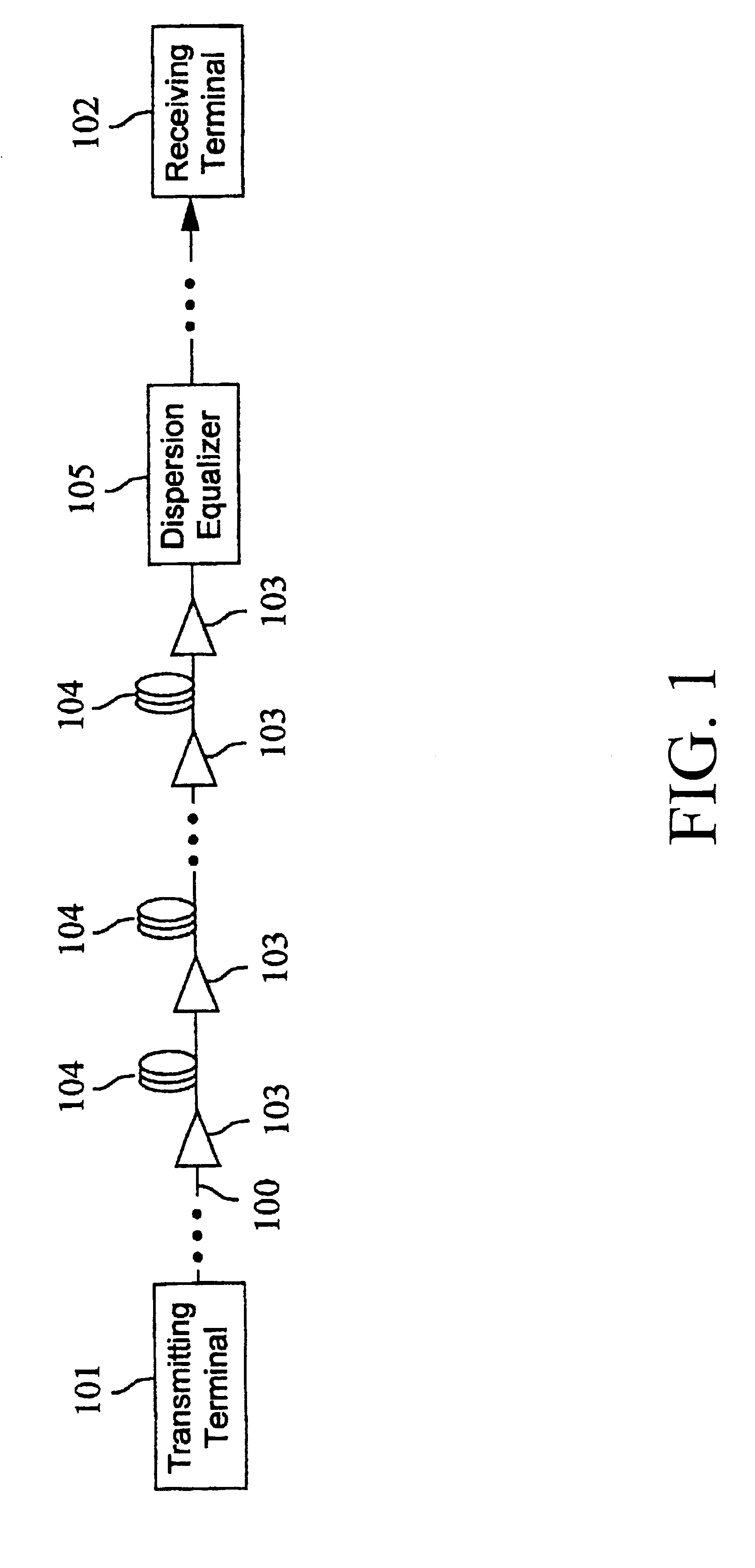
FIG. 1 shows a simplified block diagram of an exemplary optical fiber transmission system in accordance with the present invention. The system includes an optical transmission path 100, a transmitting terminal 101, and a receiving terminal 102. The transmitting terminal 101 provides an optical data signal that is to be transmitted to the remote receiving terminal via the optical fiber transmission path 100. The optical signal presented by the terminal 101 to the transmission path 100 may comprise a plurality of WDM optical carries each carrying an SDH signal. FIG. 1 shows a single period of the dispersion map consisting of optical amplifiers 103, spans of transmission fiber 104, and dispersion compensator 105. In a typical long-haul system, this series of components constituting the dispersion map period might be repeated a number of times over the length of the system. The optical amplifiers 103 may be EDFAs, for example, which amplify optical signals in the 1550 nm wavelength band...


PUM


Abstract

A method and apparatus is provided for managing dispersion in a WDM optical transmission system so that transmission performance is improved. The usable optical bandwidth of the transmission system is divided into sub-bands that individually undergo dispersion compensation before being re-combined. Accordingly, in comparison to known dispersion mapping techniques, more WDM data channels reside near a wavelength corresponding to the average zero dispersion wavelength.

Description

FIELD OF THE INVENTIONThe invention relates to the optical transmission of information and, more particularly, to a method and apparatus for compensating for chromatic dispersion that accrues over optical fiber transmission systems.BACKGROUND OF THE INVENTIONThe availability of high performance optical amplifiers such as the Erbium-Doped Fiber-Amplifier (EDFA) has renewed interest in the use of wavelength division multiplexing (WDM) for optical transmission system. In a WDM transmission system, two or more optical data carrying channels are combined onto a common path for transmission to a remote receiver. Typically, in a long-haul optical fiber system, the set of wavelength channels would be amplified simultaneously in an optical amplifier based repeater. The Erbium-Doped Fiber-Amplifier is particularly useful for this purpose because of its ability to amplify multiple wavelength channels without crosstalk penalty.Typically, it is advantageous to operate long-haul transmission syst...

Claims


Application Information

Patent Timeline
Patent Type & Authority Patents(United States)
IPC IPC(8): H04B10/18G02B6/34H04J14/02
CPCG02B6/2932G02B6/29394H04B10/2519H04B10/2525H04B2210/258H04J14/02
Inventor BERGANO, NEAL S.
Owner TYCO ELECTRONICS SUBSEA COMM LLC
Features
  • R&D
  • Intellectual Property
  • Life Sciences
  • Materials
  • Tech Scout
  • Unparalleled Data Quality
  • Higher Quality Content
  • 60% Fewer Hallucinations
Learn More