Remote brake release mechanism for an elevator machine

a technology of brake release mechanism and elevator machine, which is applied in the direction of elevators, hoisting equipment, transportation and packaging, etc., can solve problems such as difficulty in accessing locations, and achieve the effects of reducing braking force, reducing braking force, and limited and controlled movement of elevator cars

Inactive Publication Date: 2005-10-18
OTIS ELEVATOR CO
View PDF13 Cites 4 Cited by
  • Summary
  • Abstract
  • Description
  • Claims
  • Application Information

AI Technical Summary

Benefits of technology

[0007]The advantage of the invention is that in the event of a loss of power, which will cause the machine brake to engage the machine shaft, a mechanic may use the means to reduce the braking force to permit limited and controlled movement of the machine shaft, and thereby limited and controlled movement of the elevator car. The movement of the elevator car can be used to move the elevator car to a landing and permit evacuation of the elevator car. In addition, since the means is located remotely from the elevator machine, there is no need to get direct access to the machine and therefore the machine may be located in a difficult to access location, such as the overhead space in a hoistway.
[0008]In a particular embodiment, the means to reduce braking force includes a release lever disposed proximate to the brake lever and a rope engaged with the release lever and extending to a remote location relative to the elevator machine. Tensile force on the rope urges the release lever to move the brake lever against the bias of the brake lever and thereby remove the braking force on the shaft. This particular embodiment provides the advantage of a simple design and one which takes advantage of the mechanical leverage of the lever mechanism.
[0009]The foregoing and other objects, features and advantages of the present invention become more apparent in light of the following detailed description of the exemplary embodiments thereof, as illustrated in the accompanying drawings.

Problems solved by technology

In addition, since the means is located remotely from the elevator machine, there is no need to get direct access to the machine and therefore the machine may be located in a difficult to access location, such as the overhead space in a hoistway.

Method used


Image

  • Remote brake release mechanism for an elevator machine
  • Remote brake release mechanism for an elevator machine
  • Remote brake release mechanism for an elevator machine

Examples


Embodiment Construction

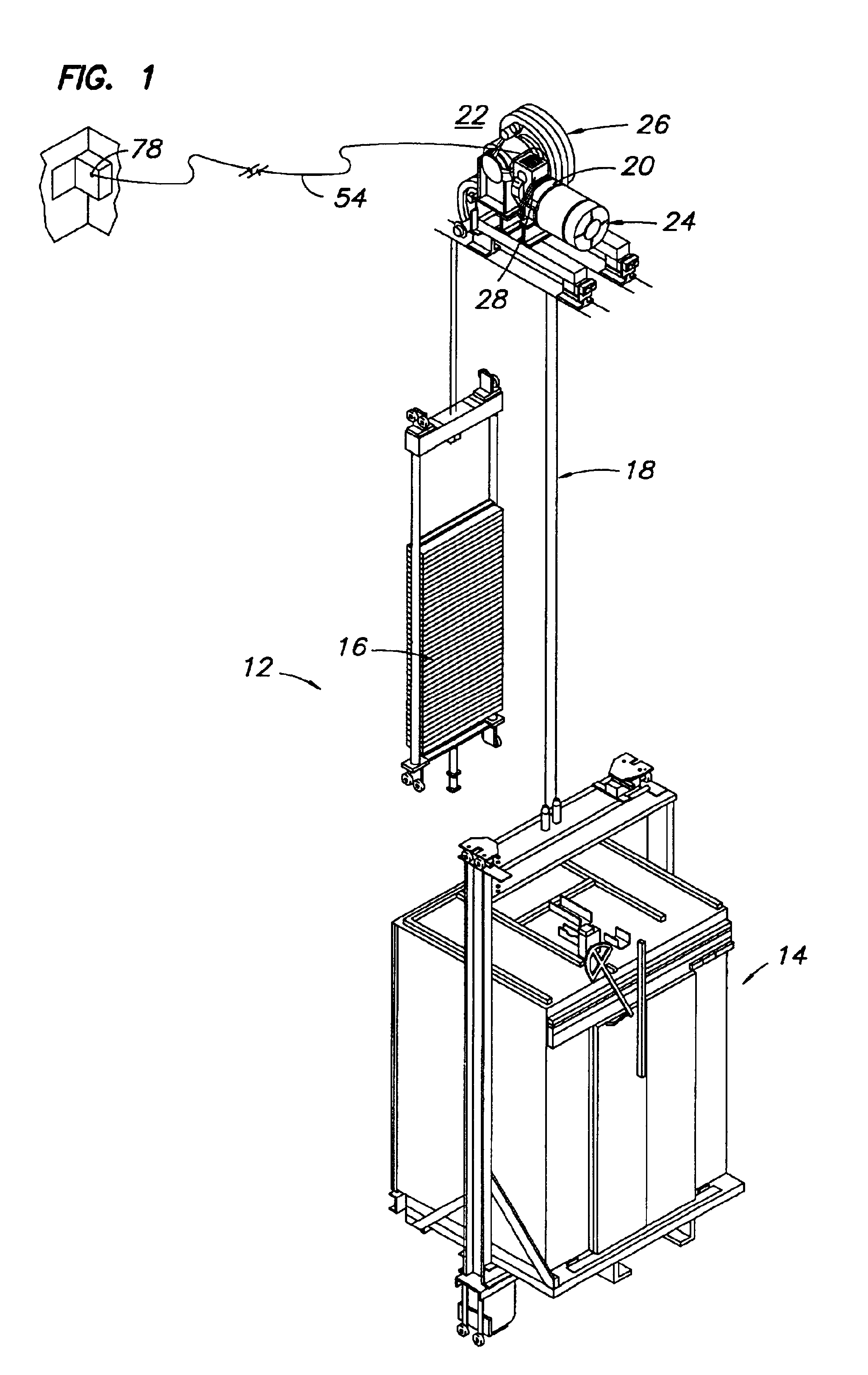
[0012]Illustrated in FIG. 1 is an elevator system 12 having a car 14, a counterweight 16, a plurality of ropes 18 interconnecting the car 14 and counterweight 16, and a traction machine 20 disposed in the overhead space 22 of the elevator system 12. The overhead space 22 is defined as the space between the top of the car 14 and the top of the hoistway with the car 14 at its highest position. Placing the traction machine 20 in this location permits the elimination of a separate machine-room.

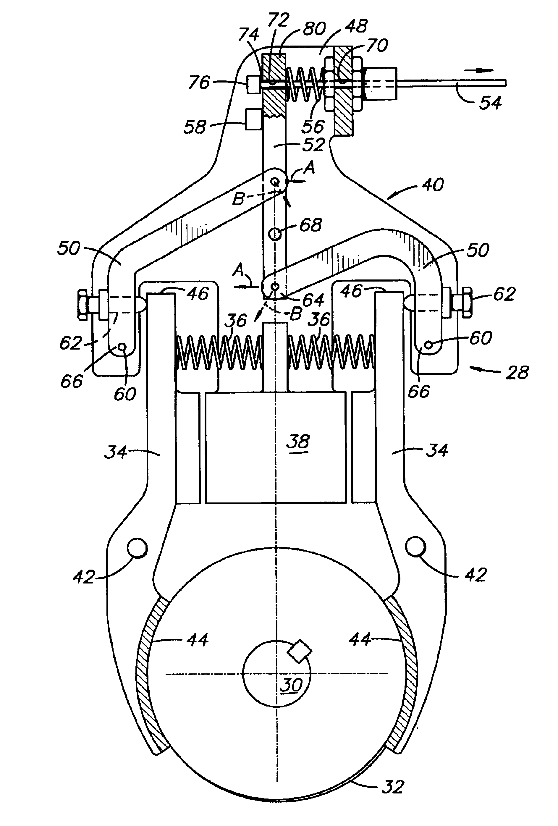
[0013]The traction machine 20 includes a motor 24, traction sheave 26 and a brake assembly 28. The motor 24 drives the traction sheave 26, which is engaged with the ropes 18 to move the car 14 and counterweight 16 through the hoistway. The brake assembly 28 is engaged with an output shaft 30 of the motor 24 to hold the traction sheave 26 against movement when the car 14 is stopped.

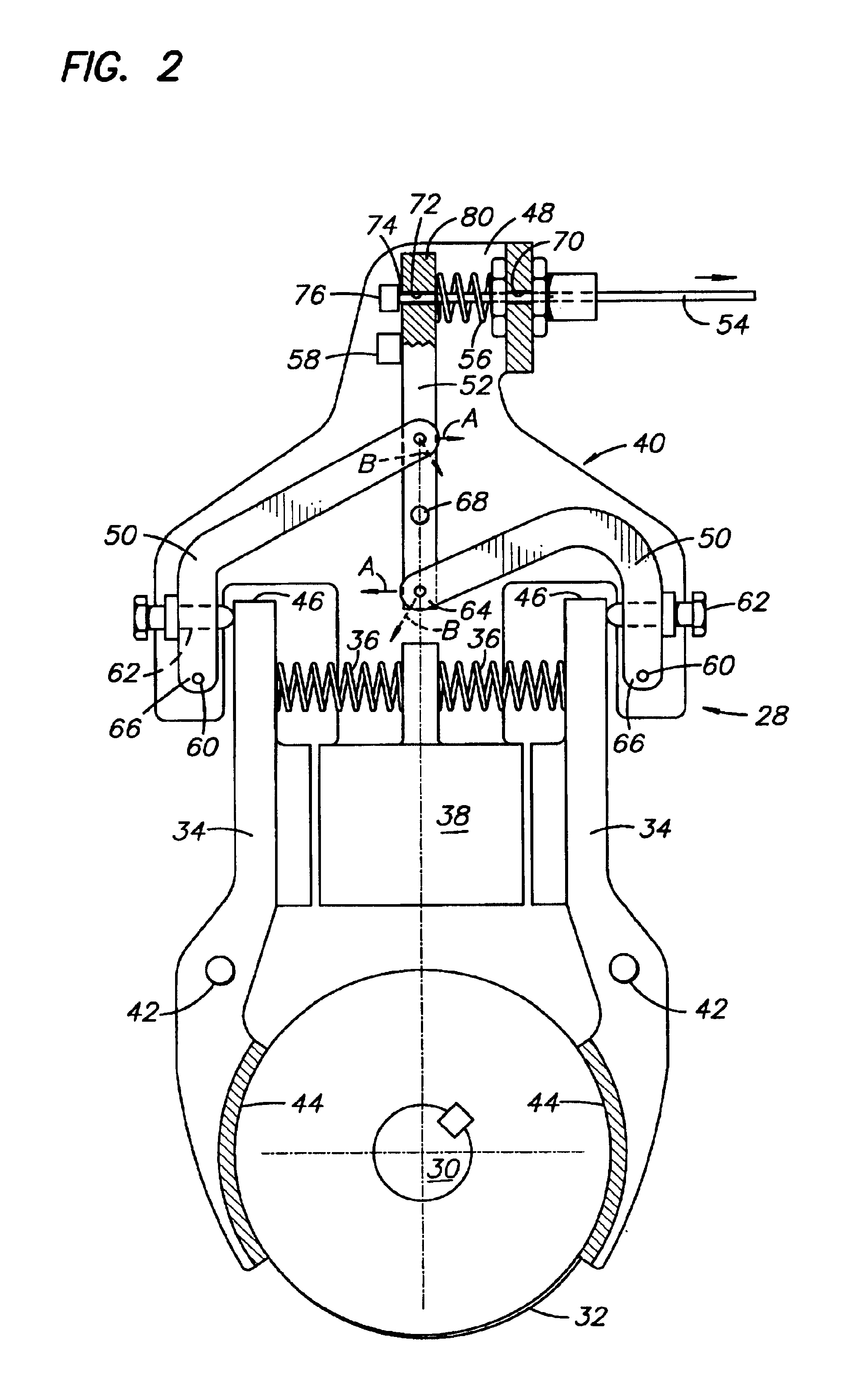
[0014]The brake assembly 28 is illustrated in more detail in FIG. 2. The brake assembly 28 includes a brake drum 32 th...


PUM


Abstract

A brake release mechanism for an elevator machine includes apparatus to reduce the braking force on the machine shaft. The apparatus may be actuated from a position located remotely from the machine.

Description

TECHNICAL FIELD[0001]The present invention relates to elevator systems, and more particularly to brake mechanisms for elevator machines.BACKGROUND OF THE INVENTION[0002]A traditional elevator system for mid-rise and high-rise buildings includes a car and a counterweight interconnected by a rope and a traction machine engaged with the rope to drive the car and counterweight. The traction machine includes a sheave engaged with the rope, an electric motor for rotating the sheave, and a brake to hold the sheave when the car is stopped. The traction machine, along with an electronic controller for the elevator system and electronic drive for the machine, are housed in a machine-room located above the hoistway.[0003]Various configurations have been suggested to eliminate the machine-room in an effort to save on the associated construction costs. One suggested elevator system uses a linear induction motor driven elevator; another uses a traction machine having a disc type motor mounted in ...

Claims


Application Information

Patent Timeline
Patent Type & Authority Patents(United States)
IPC IPC(8): B66D5/00B66D5/08B66D5/24B66B5/02
CPCB66B5/027B66D5/08B66D5/24
Inventor SEVILLEJA, JOSESANDOVAL, JOSE M.
Owner OTIS ELEVATOR CO
Why Eureka
Try Eureka