Reinforced composite structure

a composite structure and reinforced technology, applied in the direction of prosthesis, blood vessels, knitting, etc., can solve the problems of limiting the use of the trunk, applicants are not aware of any of the services and applicants are not aware of the use of pressurized tank structures. achieve the effect of light weigh

Inactive Publication Date: 2007-04-10
SPECTRUM SOLUTIONS
View PDF43 Cites 7 Cited by
  • Summary
  • Abstract
  • Description
  • Claims
  • Application Information

AI Technical Summary

Benefits of technology

[0014]The pressurized natural gas tank construction of the present invention has the advantage of being light in weight and capable of confining the pressurized gas. The construction permits the tank to be made in any geometric shape and, preferably, in a noncylindrical, prismatic shape comprised of a number of intersecting generally flat faces or surfaces. Therefore, the walls of the tank can conform to any available space in a vehicle for a tank.

Problems solved by technology

Since the cylindrical steel natural gas storage tank is not suitable for and cannot be readily retrofitted in place of the vehicle's liquid fuel storage tank, the natural gas storage tank is often housed in the storage area or trunk of the vehicle, thereby eliminating or severely limiting the use of the trunk for other storage.
In contrast, the Pechstein '400 and Albrecht '414 patents are designed to store large volumes of pressurized gas and are not designed for portability.
None of the above tanks provide a tank structure that may be constructed in any desired shape as may be required for installation in a vehicle.
Further, Applicants are not aware of any of those pressurized tank structures serving any purpose other than holding a pressurized liquid or gas.

Method used


Image

  • Reinforced composite structure
  • Reinforced composite structure
  • Reinforced composite structure

Examples


example

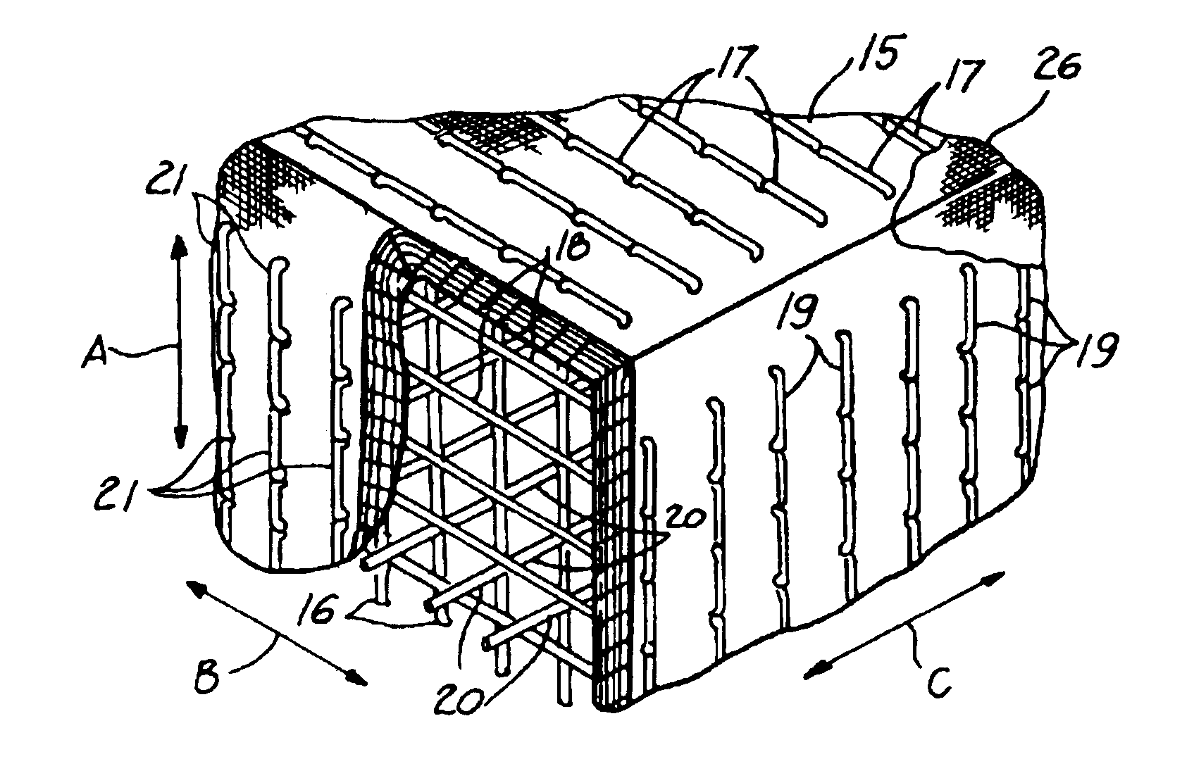
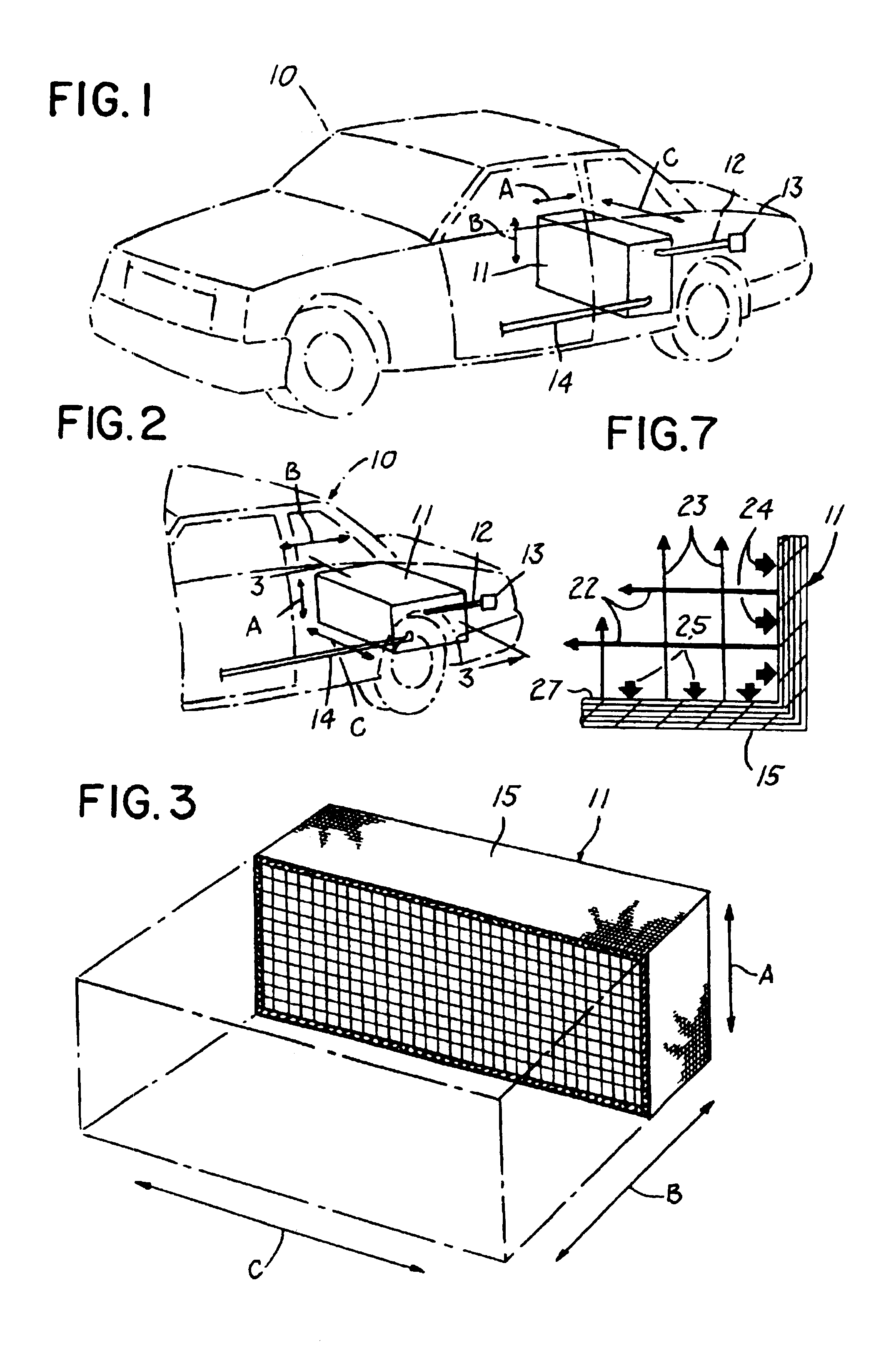
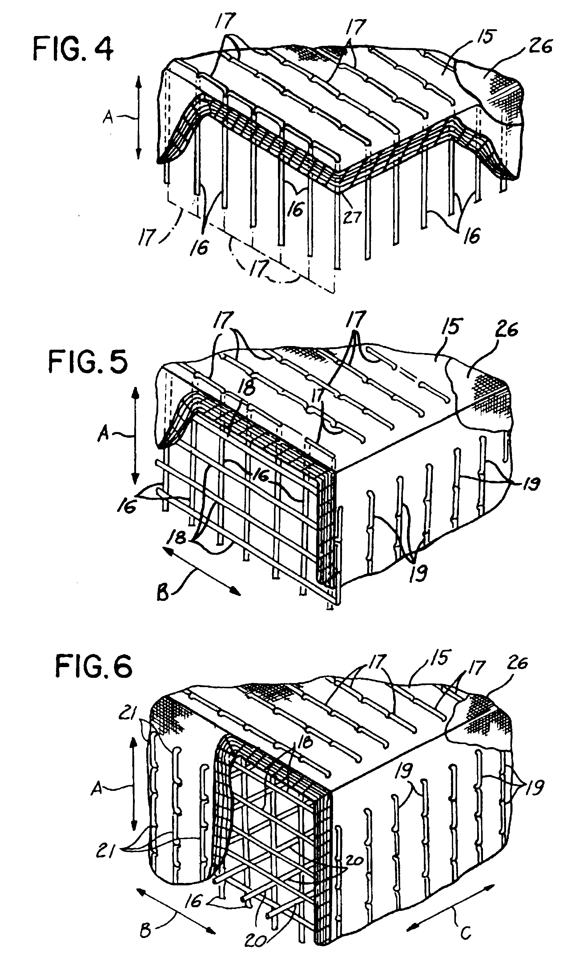
[0044]First, a core was formed from a piece of one inch thick foam cut into a six inch by six inch square. The edges of the form were rounded, using a one-half inch router bit, thereby creating a foam square with smooth semicircular edges having a one-half inch radius and two opposed five inch by five inch surfaces Notches were cut at the center of two opposed curved edges to receive metal inserts. The metal inserts were made from a two inch long, one inch diameter piece of aluminum rod that was sawed in half longitudinally to create an insert with a semicircular cross-section. A longitudinal center hole was drilled through the metal inserts, and the holes were tapped to accept a ⅛ pipe. The meal inserts were then inserted into the notches so that their ends were flush with the surface of the curved edge.

[0045]Next, three piles of three ounce per square yard E-glass woven fabric were wrapped around the core, followed by three plies of twenty ounce E-glass woven fabric. The second se...


PUM

PropertyMeasurementUnit
anglesaaaaaaaaaa
thickaaaaaaaaaa
radiusaaaaaaaaaa

Abstract

A reinforced composite structure (29) is disclosed. The structure is formed by opposed layers of material extending over a core and continuous bundles stitched in a repeating pattern through the opposed layers (30, 32) and the intermediate core (29) to form the reinforced composite structural member (29).

Description

[0001]This is a continuation-in-part of application Ser. No. 08 / 568,197 filed on Dec. 6, 1995 and entitled TANK FOR STORING PRESSURIZED GAS, now U.S. Pat. No. 5,647,503, which is a continuation-in-part of application Ser. No. 08 / 297,232 filed Aug. 29, 1994 and entitled NON-CYLINDRICAL FUEL TANKS FOR NATURAL GAS VEHICLES, now abandoned.FIELD OF THE INVENTION[0002]The present invention relates generally to the construction of reinforced composite structures, and more particularly, to a composite sandwich structure member.BACKGROUND OF THE INVENTION[0003]For many years, there has been interest in developing and using alternative fuels for vehicles, and particularly, overland vehicles, for example, automobiles, buses, trucks, etc Over that period of time, many such vehicles have been retrofitted to operate using natural gas. More recently, with increasingly stringent air pollution standards, fleets of vehicles that have been retrofitted to operate with natural gas are more common.[0004]...

Claims


Application Information

Patent Timeline
Patent Type & Authority Patents(United States)
IPC IPC(8): B32B3/06B29C45/00
CPCB29C70/543B29C70/865Y10T428/24182Y10T428/24033Y10T428/24174
Inventor STEELE, ROBIN S.STENGER, JENNIFER L.
Owner SPECTRUM SOLUTIONS
Why Eureka
Try Eureka