Modular sleeve

a module and sleeve technology, applied in the field of modular sleeves, can solve the problems of reducing the service life of the gun barrel, the inability to adapt to the rigid environment of laser operations, and the inability to quickly destroy lasers and ancillary optics and electronics, so as to facilitate internal fastening, reduce the size, and eliminate the effect of exposed cables

Inactive Publication Date: 2008-04-08
SWAN RICHARD E
View PDF22 Cites 110 Cited by
  • Summary
  • Abstract
  • Description
  • Claims
  • Application Information

AI Technical Summary

Benefits of technology

[0007]In view of the foregoing disadvantages inherent in the known types of devices now present in the prior art, the present invention provides a modular receiver sleeving system. As such, the general purpose of the present invention, which will be described subsequently in greater detail, is to provide a new and improved interface means for firearms which will isolate the gun barrel while providing various capabilities for mounting and integrating optics, lasers and sensors. Included in the invention capabilities are integral fastening fixtures and special contouring to facilitate internal fastening of laser housings adapted to plug into electrical sockets contained in the invention. This reduces size and eliminates exposed cables.

Problems solved by technology

The problem with integrating laser technology to firearms is the inherent conflict between a gun barrel's physical functioning and the rigid environment required for laser operations.
The temperature of a gun barrel in use can rise to 900° F. This type of heat, as well as the physical shock on the gun barrel from firing, will quickly destroy lasers and ancillary optics and electronics.
Further compounding this problem is the requirement that gun barrels be extra heavy to support the added weight attached by means of the collars.
The combination of heat and barrel weight tend to pull the barrel chamber out of alignment with the bolt lead, thereby causing bolt lug and extractor failure.

Method used


Image

  • Modular sleeve
  • Modular sleeve
  • Modular sleeve

Examples


Embodiment Construction

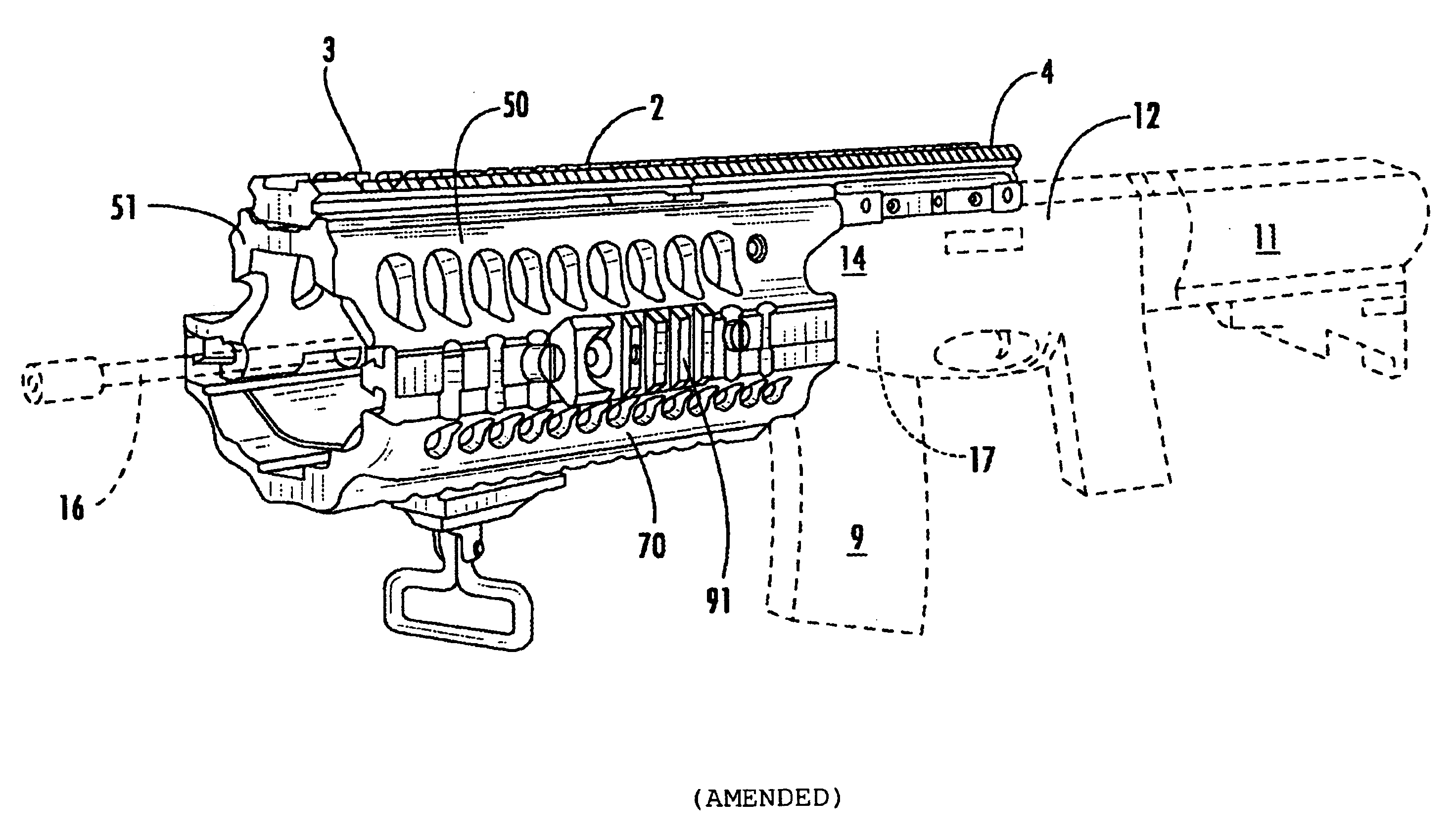
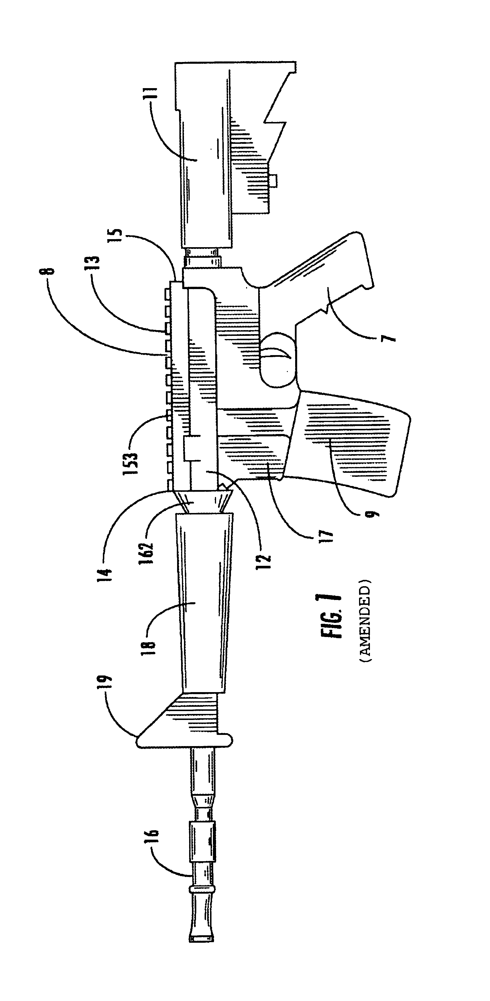
[0033]Referring to the drawings in detail wherein like elements are indicated by like numerals, there is shown in FIG. 1 an outline of a conventional combat firearm 10 having a conventional stock 11, upper receiver 12 with flat top 13, lower receiver 17, barrel 16, pistol grip 7, and magazine 9. The barrel 16 is joined to the upper receiver 12. The barrel 16 defines the forward portion of the firearm 10 and the stock 11 defines the rearward portion of the firearm 10. The longitudinal axis of the firearm 10 runs from stock 11 through receiver 12, 17 to barrel 16. The barrel 16 is joined to the forward portion 14 of the upper receiver 12, i.e., the upper receiver 12“receives” the barrel 16. The stock 11 is joined to the rear portion 15 of the upper receiver 12. The barrel 16 has protective handguards 18 about its circumference.

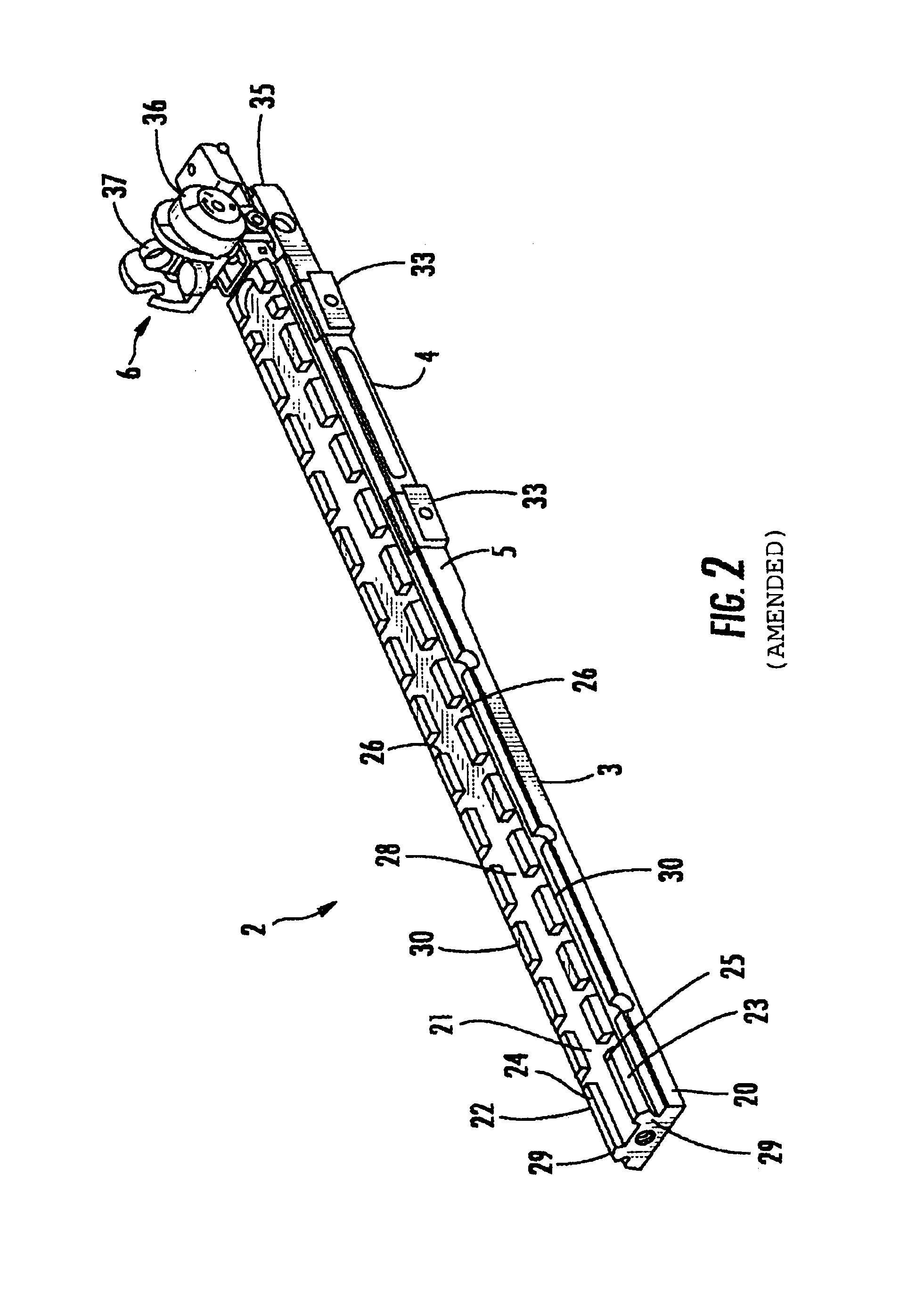
[0034]The present invention provides a modular sleeve 1 about the firearm barrel 16 replacing the firearm's conventional handguards with a handguard assembly in...


PUM


Abstract

A Swan universal receiver sleeve attached to the top of a firearm upper receiver and extended forward above the firearm barrel to a position just short of the firearm front sight. The underside of the rear portion of the sleeve is fixedly attached to the receiver top. The underside of the forward portion of the sleeve has an upper handguard piece attached thereto. A bottom handguard piece is fitted about the bottom of the gun barrel and is attached to the upper handguard piece. The handguard pieces are not physically connected in any way to the gun barrel. The sleeve is self supported by the connection of the rear portion underside to the receiver top.

Description

[0001]This application claims the benefit of Provisional Application No. 60 / 274,147, filed Mar. 9, 2001.BACKGROUND OF THE INVENTION[0002]This invention relates to integration means, and more particularly to a device added to a firearm for incorporating ancillary equipment.[0003]As the field of combat and commercial weaponry expands, numerous add-on enhancements have become available for attachment to standard firearms thereby significantly upgrading the capability of the firearm. Various methods and means have been developed for interfacing the various add-on enhancements to firearms. Applicant's U.S. Pat. No. 4,845,871, discloses a quickly detachable interface means for modular enhancements. Applicant's U.S. Pat. No. 5,142,806 discloses a universal receiver sleeve having an upper interface portion with standard, universal dimensions regardless of the firearm and having a lower interface portion specific to a particular firearm. Applicant's U.S. Pat. No. 5,343,650 discloses an exten...

Claims


Application Information

Patent Timeline
Patent Type & Authority Patents(United States)
IPC IPC(8): F41C23/00F41C23/16F41G1/387
CPCF41C23/00F41C23/16F41G11/003
Inventor SWAN, RICHARD E.
Owner SWAN RICHARD E
Why Eureka
Try Eureka