Synchronizing signal separating apparatus and method

a technology of synchronizing signal and separation apparatus, which is applied in the field ofsignal processing systems, can solve the problems of high cost of video signal processing and the reproduction of video signals, and achieve the effect of reducing the cost of making these video devices and simplifying the design and manufacture of video devices

Inactive Publication Date: 2008-07-01
COOPER J CARL
View PDF67 Cites 4 Cited by
  • Summary
  • Abstract
  • Description
  • Claims
  • Application Information

AI Technical Summary

Benefits of technology

[0021]The synchronizing signal processing apparatus in accordance with the present invention may be used with different video devices, which simplifies the design and manufacture of video devices, and significantly decreases the cost to make these video devices.
[0022]Another advantage of the synchronizing signal processing apparatus of the present invention is that it is suitable to be implemented by integrated circuits. Alternatively, the video signal processing can be implemented by software, such as in signal processing applications. These and other features and advantages of the present invention are apparent from the description below with reference to the following drawings.

Problems solved by technology

In addition, these circuits must separate this information from noise and interference during the reception of weak signals, particularly if impulse noise is present.
Conventional video signal devices for processing the synchronizing information of the video signals can not be used for different standard video signals for providing reliable synchronizing signals, without affecting the reproduction of the video signals or causing high cost of video signal processing.

Method used


Image

  • Synchronizing signal separating apparatus and method
  • Synchronizing signal separating apparatus and method
  • Synchronizing signal separating apparatus and method

Examples


Embodiment Construction

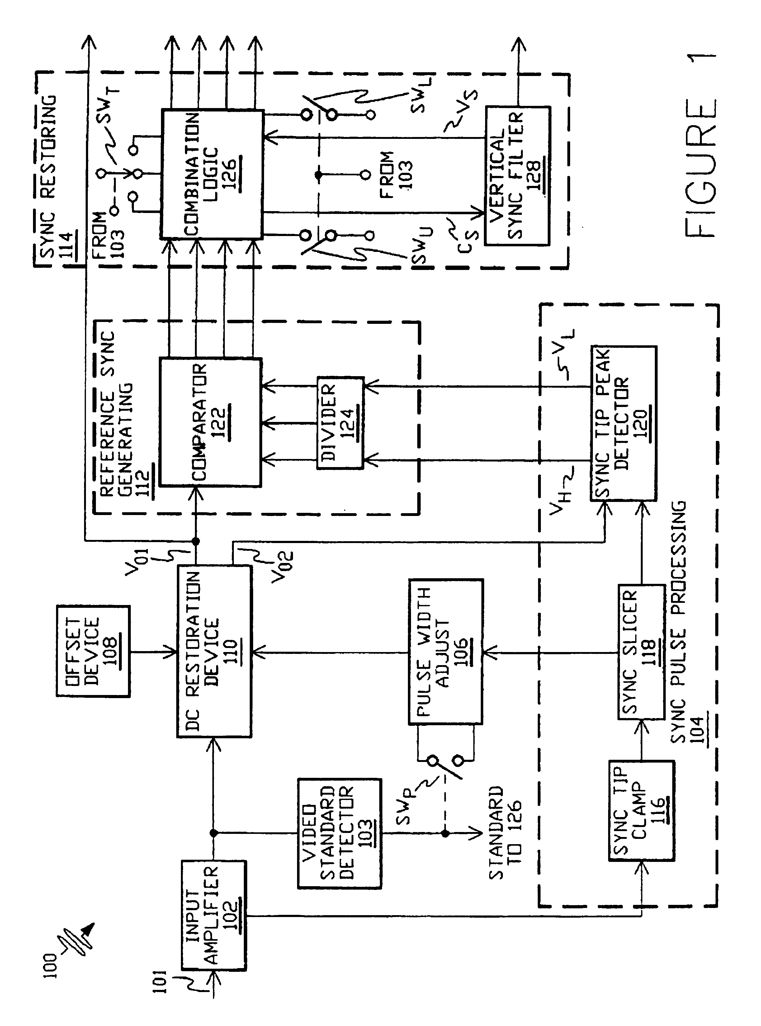
[0041]A synchronizing signal processing apparatus 100 in accordance with the present invention includes an input amplifiedamplifier 102, a video standard detector 103, a sync pulse processing section 104, a pulse width adjust 106, an offset device 108, a DC (Direct Current) restoration device 110, a reference sync generating section 112 and a sync restoring section 114.

[0042]Video signal 116101is applied to differential input amplifier 102 where video signal 101 is amplified to improve the ratio of signal / common mode noise. The video signal amplified by input amplifier 102 is fed to sync pulse processing section 104 which includes a sync tip clamp 116, a sync slicer 118 and a sync tip peak detector 120.

[0043]The video signal is first clamped by sync tip clamp 116 to generate a clamped signal which has a known DC level of the synchronizing pulses. The clamped signal is then transferred to sync slicer 118 where the clamped signal is sliced, thereby generating a signal that has the sam...


PUM


Abstract

This invention is a method and apparatus for identifying and separating the synchronizing signal component of video like signals by identifying or detecting the arrangement or sequence of the known occurances of events or patterns of the sync. The invention also provides for establishing data slicing references in response to the levels of known portions of the sync component.

Description

[0001]This application is a continuation-in-part of application Ser. No. 08 / 493,661, filed Jun. 22, 1995, now abandoned which is continuation in part of U.S. patent application Ser. No. 08 / 165,688 filed Dec. 13, 1993 now U.S. Pat. No. 5,486,869<?insert-start id="INS-S-00001" date="20080701" ?>, which is a continuation of application Ser. No. 07 / 837,323, filed Feb. 18, 1992, now abandoned.BACKGROUND OF THE INVENTION[0002]The present invention relates to signal processing systems and, in particularlyparticular, to video signal processing. A major objective of the present invention is a synchronizing signal processing apparatus and a method that precisely recovers synchronizing signals of a video signal.[0003]Much of modern technology depends on signal processing. A common application of signal processing is for the video type signals. Usually, a video type signal includes an information signal component and picture or data synchronizing information comprisedcomponent. The sync...

Claims


Application Information

Patent Timeline
Patent Type & Authority Patents(United States)
IPC IPC(8): H04N5/08H04N5/10
CPCH04N5/08
Inventor COOPER, J. CARL
Owner COOPER J CARL
Why Eureka
Try Eureka