Pulsed flow for capacity control

a technology of capacity control and pulse flow, which is applied in the direction of positive displacement liquid engines, subcoolers, light and heating apparatus, etc., can solve the problems of expensive motor driven modulation valves or only the control of steps, and achieve the effect of less expensiv

Inactive Publication Date: 2008-09-16
CARRIER CORP
View PDF30 Cites 4 Cited by
  • Summary
  • Abstract
  • Description
  • Claims
  • Application Information

AI Technical Summary

Benefits of technology

[0005]It is a further object of this invention to provide a less

Problems solved by technology

One problem associated with these arrangements is that capacity can only be controlled in steps or expensive mot

Method used


Image

  • Pulsed flow for capacity control
  • Pulsed flow for capacity control

Examples


Embodiment Construction

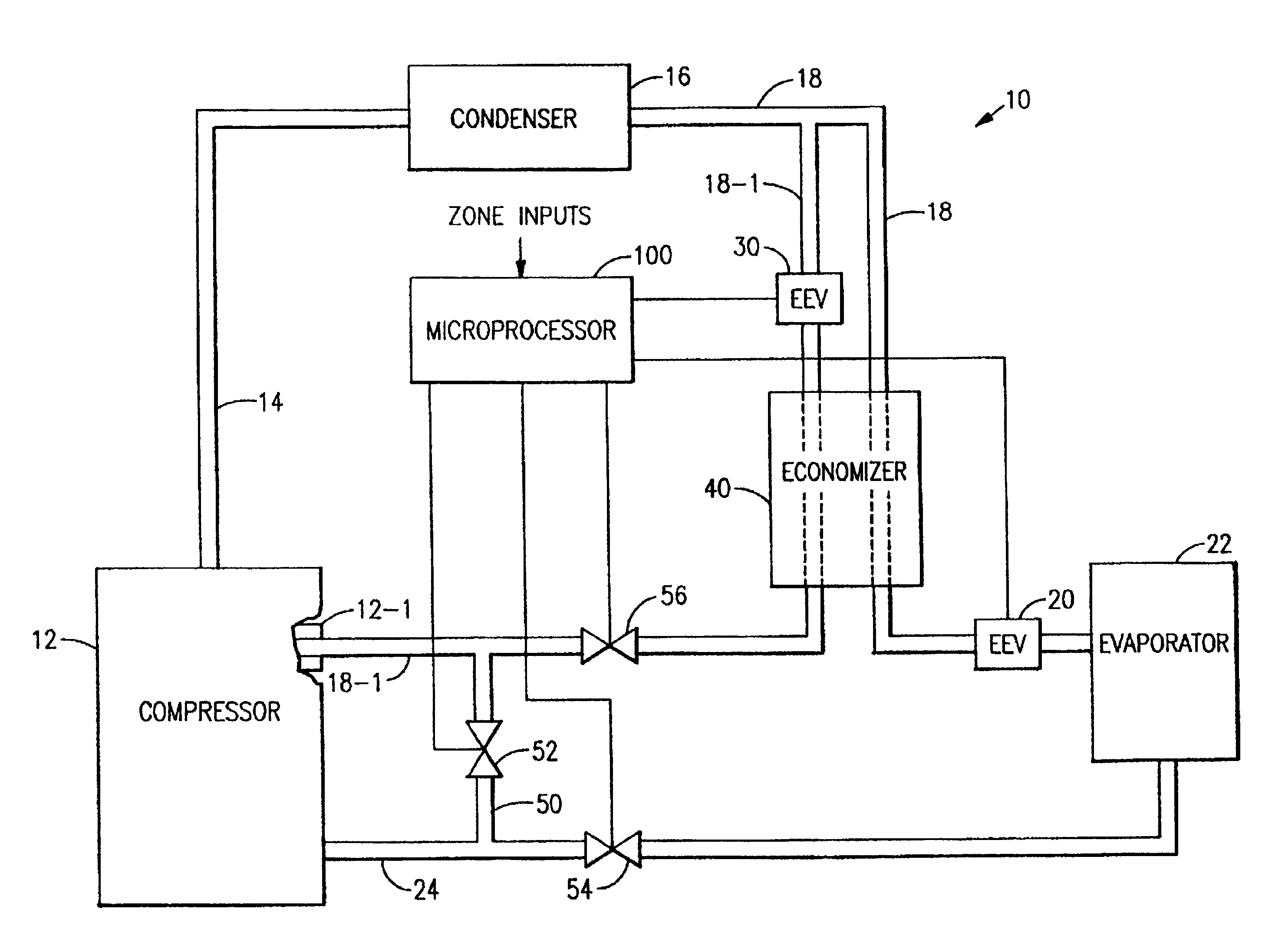
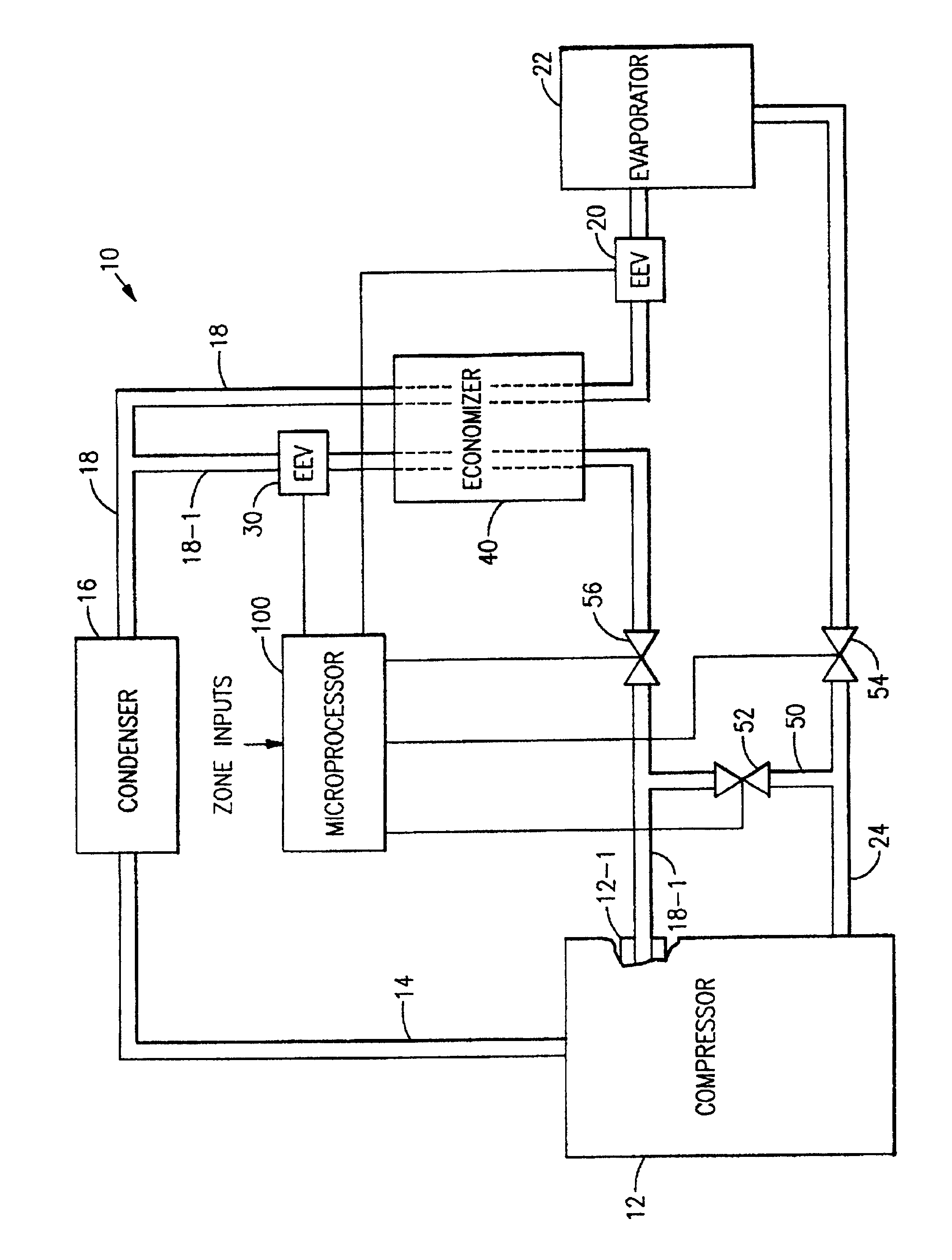
[0010]In the FIGURE, the numeral 12 generally designates a hermetic compressor in a closed refrigeration or air conditioning system 10. Starting with compressor 12, the system 10 serially includes discharge line 14, condenser 16, line 18, expansion device 20, evaporator 22, and suction line 24 completing the circuit. Line 18-1 branches off from line 18 and contains expansion device 30 and connects with compressor 12 via port 12-1 at a location corresponding to an intermediate point in the compression process. Economizer heat exchanger 40 is located such that line 18-1, downstream of expansion device 30, and line 18, upstream of expansion device 20, are in heat exchange relationship. The expansion devices 20 and 30 are labeled as electronic expansion devices, EEV, and are illustrated as connected to microprocessor 100. In the case of expansion device 20, at least, it need not be an EEV and might, for example, be a thermal expansion device, TEV. What has been described so far is gener...


PUM


Abstract

Step control in capacity modulation of a refrigeration or air conditioning circuit is achieved by rapidly cycling a solenoid valve in the suction line, economizer circuit or in a bypass with the percent of “open” time for the valve regulating the rate of flow therethrough. A common port in the compressor is used for economizer flow and for bypass.

Description

BACKGROUND OF THE INVENTION[0001]In a closed air conditioning or refrigeration system there are a number of methods of unloading that can be employed. Commonly assigned U.S. Pat. No. 4,938,666 discloses unloading one cylinder of a bank by gas bypass and unloading an entire bank by suction cutoff. Commonly assigned U.S. Pat. No. 4,938,029 discloses the unloading of an entire stage of a compressor and the use of an economizer. Commonly assigned U.S. Pat. No. 4,878,818 discloses the use of a valved common port to provide communication with suction for unloading or with discharge for Vi control, where Vi is the discharge pressure to suction pressure ratio. In employing these various methods, the valve structure is normally fully open, fully closed, or the degree of valve opening is modulated so as to remain at a certain fixed position. One problem associated with these arrangements is that capacity can only be controlled in steps or expensive motor driven modulation valves must be emplo...

Claims


Application Information

Patent Timeline
IPC IPC(8): F25B3/00F04B49/00F25B1/00F25B41/00F25B1/10F25B40/02F25B41/04
CPCF25B40/02F25B2400/13F25B2600/2509F25B2600/2521F25B41/22F25B49/02F25B2400/04
Inventor LIFSON, ALEXANDER
Owner CARRIER CORP
Why Eureka
Try Eureka